semi合集-English.pdf - 第4594页
SEMI D35-1103 E © SEMI 2003 6 each point to be measured. Fix the lamp and move the spectrora diometer or the colorimeter for better measurement since the lamp wall temperature does not vary an d so the luminance becomes …

SEMI D35-1103
E
© SEMI 2003 5
Me asure me nt St arte d
±3%
Overcurrent
Luminanc e
100%
0
S
Figure 4
Measuring Time of Optical Characteristics
Commentary on Figure 4: The CCFL luminance has a special rising property. The highest luminance and stable
luminance vary by the combination of ambient temperature and lamp current and the transitions vary as well. This is
based upon the fact that the CCFL luminance depends on temperature and the generated heat by lighting affects it.
For this reason, the luminance varies until the lamp wall temperature becomes stable. Before the measurement, grasp
the special rising property of luminance and set the timing of measurement of the stable luminance.
9.2.4 Measurement of Luminance — Set a spectroradiometer or a colorimeter vertical to a side to be measured and
measure according to the above-mentioned instruction of measurement. Avoid shades of mercury particles in the
lamp. (See Figure 5.)
Station Diame
t
Lamp insi
d
diamete
Lamp outsi
d
diamete
M ercury Grain
(Within 50%
inner diame
t
Station Diameter
(Within 50% of
inner diameter)
Lamp inner
diameter
Lamp outer
diameter
Figure 5
Measuring Spot (Diameter) for Optical Characteristics
9.2.5 Measurement of Chromaticity — Measure in the same manner and at the same time of the measurement of
luminance.
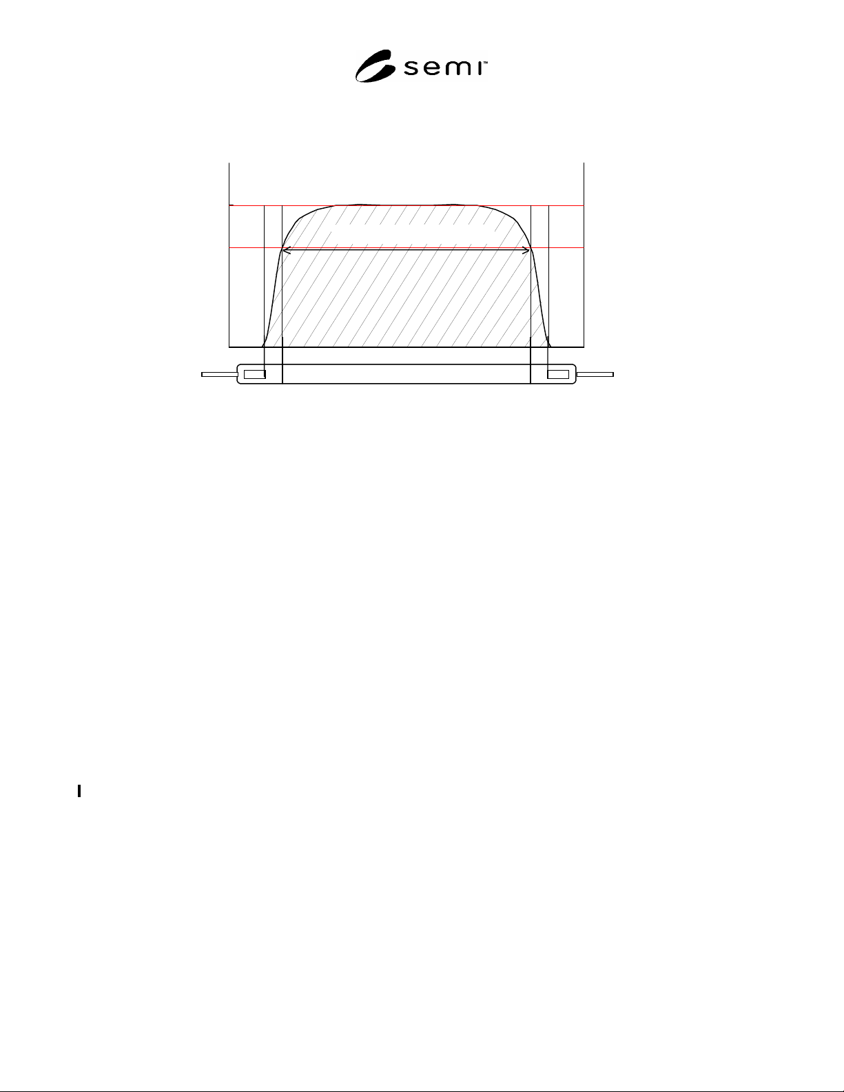
9.3 Measurement of Effective Length of Luminous Part — Measure when the luminance is fully stable at a specified
lamp current according to the measuring conditions mentioned above. The luminance varies greatly around
electrodes since the temperature variation is big among points of measurement due to high temperature of a lamp
wall. Sufficient aging shall be performed before measurement to avoid impacts of the change of passage of time to
SEMI D35-1103
E
© SEMI 2003 6
each point to be measured. Fix the lamp and move the spectroradiometer or the colorimeter for better measurement
since the lamp wall temperature does not vary and so the luminance becomes stable in this way. (See Figure 6.)
100%
0
mm
Luminance
Effective length of luminous part
70%
Figure 6
Measurement of Effective Length of Luminous Part
9.4 Measurement of Luminance Stabilization Time —
Use a CCFL in which the wall temperature and ambient
temperature are kept in equilibrium before lighting.
From just after a CCFL is turned on by specified lamp
current, measure the luminance changes until it seems
stable (where the luminance fluctuation difference is
within ± 3% of the stable luminance, for example).
10 Reporting Results
10.1 Report the following items:
10.1.1 report date,
10.1.2 test date,
10.1.3 measuring equipment types, and conditions of
use (lighting frequency, rated length of connecting
wire, distance of measurement, viewing angle, etc.),
10.1.4 conditions of test specimen (size, other
specifications, etc.),
10.1.5 to specify item names and necessary entries for
the CCFL outer and inner diameters, lamp length and
necessary specifications,
10.1.6 conditions of measurement (ambient
temperature, aging time, etc.),
10.1.7 measurement results (electrical and optical
characteristics), and
10.1.8 remarks (other notes).
11 Related Documents
Related Information 1: documents regarding main
discharge,
Related Information 2: dark characteristics, and
Related Information 3: precautions for measuring
method (leakage current, lamp wall temperature,
temperature slide-up speed for master CCFL, etc.).
NOTICE: SEMI makes no warranties or
representations as to the suitability of the standards set
forth herein for any particular application. The
determination of the suitability of the standard is solely
the responsibility of the user. Users are cautioned to
refer to manufacturer's instructions, product labels,
product data sheets, and other relevant literature,
respecting any materials or equipment mentioned
herein. These standards are subject to change without
notice.
By publication of this standard, Semiconductor
Equipment and Materials International (SEMI) takes no
position respecting the validity of any patent rights or
copyrights asserted in connection with any items
mentioned in this standard. Users of this standard are
expressly advised that determination of any such patent
rights or copyrights, and the risk of infringement of
such rights are entirely their own responsibility.

SEMI D35-1103
E
© SEMI 2003 7
RELATED INFORMATION 1
STARTING VOLTAGE OF COLD CATHODE FLUORESCENT LAMP
(CCFL)
NOTICE: This related information is not an official part of SEMI D35 and was derived from Japan Backlight TF.
R1-1 Phenomenon of CCFL Discharge
Starting
R1-1.1 Although the phenomenon of CCFL discharge
starting shows the similarity to that of low gas pressure
discharge starting, a high frequency lighting circuit
(inverter) with approximately 30–100 kHz is mostly
used to discharge and so it is affected by stray
capacitance.
R1-1.2 When the secondary voltage of inverter is
stepping up from a sufficiently low voltage gradually,
an emission area appears near the electrode connected
to higher voltage side. (See Figure R1-1 1
st
Phase).
This means that the discharge starts between the
electrode and ground level of discharge circuit through
the stray capacitance, and a spark after dark current
takes place in the discharge space in the tube. In the
discharge, the other electrode is the tube wall (glass or
fluorescent substance); the formation of dielectric
barrier discharge and the existence of the secondary
electron supply system to the discharge space can be
considered and thus the discharge seems sustainable.
Therefore, the emission around the electrode is judged
to be the emission mainly by negative glow of glow
discharge.
R1-2 From Discharge Starting to Stable
Lighting Mode
R1-2.1 After the discharge takes place near the
electrode and the secondary voltage of the inverter
increases gradually, the emission area near the
electrode grows longer accordingly. (See Figure R1-
2.) This means that a positive column is generated by
applied voltage to have such the length as corresponds
to the value of resistance based on the applied voltage.
When the voltage is applied furthermore, the emission
area (i.e. positive column) between two electrodes is
generated finally. (See Figure R1-3 2
nd
Phase.)
However, if the tube is thin and long and the stray
capacitance is relatively greater to the discharge circuit,
the ratio of current that flows through the stray
capacitance is still large at this phase. With the
increase of the inverter secondary voltage, the ratio of
current that flows in the tube also increases and most of
the current flows in the tube because the impedance of
discharge path decreases on the contrary due to
negative characteristics of discharge. (See Figure R1-4
3
rd
Phase.)
R1-2.2 Each voltage applied at these three phases may
be called starting voltage at the first phase, or stable
discharge voltage or tube current at the third phase, for
example. Sometimes it could be hard to distinguish the
second phase from the third phase. In addition, since
the second phase is hardly observed by the tube designs
(for the tube length, outer and inner diameters of tube,
pressure and composition of filler gas, and peripheral
members of tube), it looks as if the first phase shifted to
the third phase suddenly. This is because the stray
capacitance is so big that the current cannot flow into
the tube, the discharge surges immediately after the
current flows into the tube, the impedance of the
discharge path decreases due to the negative
characteristics and a large amount of current flows in
the tube all of a sudden.
R1-2.3 From the viewpoint of discharge phenomenon,
the voltages applied to the tube at the first and third
phases are important. Especially the voltage applied at
the third phase should be noted practically. (The
voltage applied at the second phase may be noted also.)
R1-3 Cautions at Discharge Starting
R1-3.1 At the discharge starting, coefficient of
discharge gas and coefficient of electrode are
involved. These coefficients contain the pressure of
discharge gas (particle density) as a parameter.
Especially when the mercury is filled in, the control of
ambient temperature becomes very important because
the mercury vapor (particle density) pressure changes
sensitively to the ambient temperature.
R1-3.2 In addition, the lighting circuit is usually built
for AC, the reduction of unnecessary stray capacitance
base on frequency shall be required. As the impact of
stray capacitance becomes greater especially when the
tube is thin and long, sufficient consideration shall be
given.