semi合集-English.pdf - 第3223页
SEMI E127-0705 © SEMI 2003, 2005 24 original location Substrate T ransfer Path Robot handoff new locatio n y (> 0 ) x (>0) Robot handoff ( i nto page) original location new location z (>0) Figure 7 Illustr…
SEMI E127-0705 © SEMI 2003, 2005 23
state to allow the physical substrate that it did load to be removed or to receive a new UpdateSubstrateObject
message.
12.6.7.2 Any request by a client to delete a Substrate Object for a substrate physically located with the IMM in
general shall be denied.
12.7 Substrate Orientation
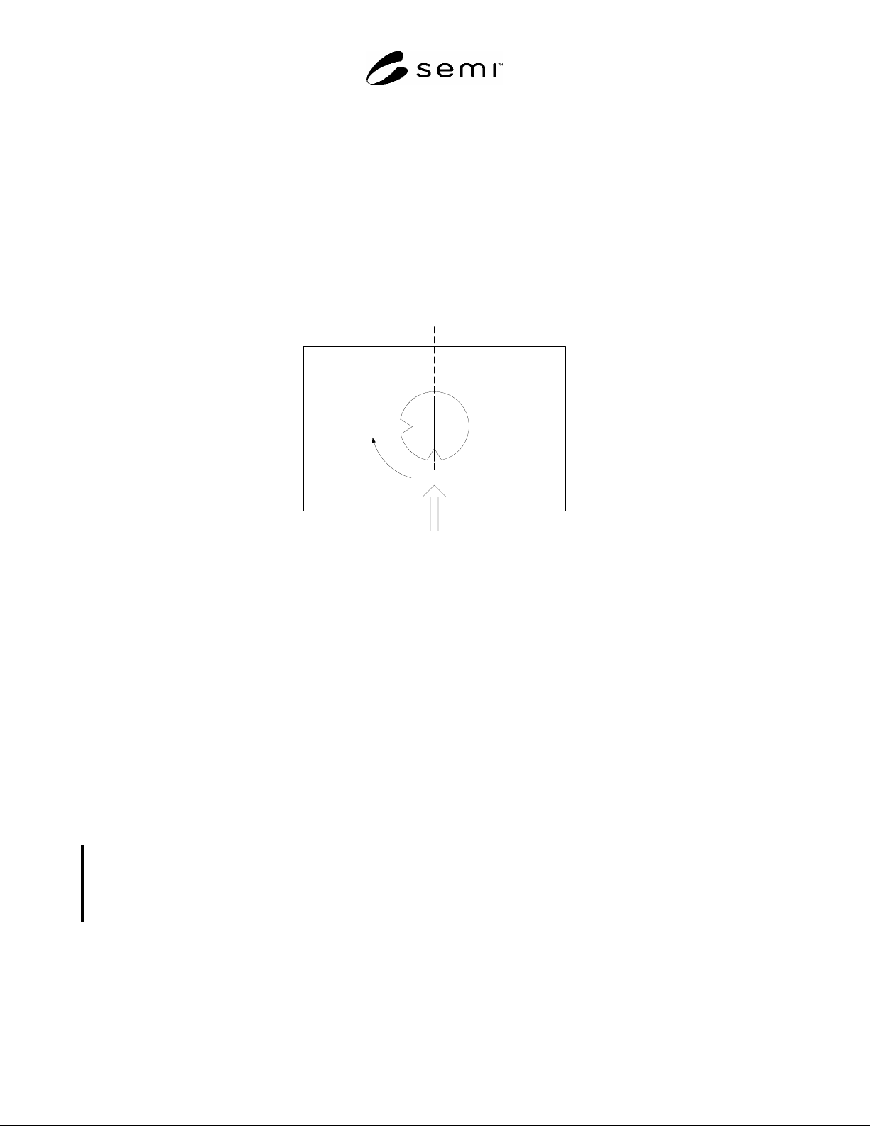
12.7.1 When a substrate is delivered to or picked up from the IMM’s STPO, the substrate has a certain orientation
with respect to the position of the fiducial relative to the entry into the STPO, as illustrated in Figure 6.
12.7.2 The Control Client is able to specify both the incoming orientation of a substrate being loaded into the STPO
and the desired outgoing orientation by passing values for the OrientationIn attribute and/or the OrientationOut
attribute in the UpdateSubstrateObject service.
0 degrees
Substrate Transfer Path
90 degrees
vertical plane
Figure 6
Illustration of Orientation
12.7.3 If the IMM is not capable of determining orientation, either within the STPO or any other of it’s components,
and if a value has been set in OrientationIn, the value in OrientationOut shall be set to the same value that was
provided in OrientationIn.
12.7.4 Otherwise, the following rules shall apply:
If neither OrientationIn nor OrientationOut are provided by the Control Client, then the IMM shall return the
substrate in the same orientation as it was received.
If OrientationIn is provided, and if the actual orientation is determined to be different, then the
“OrientationError” error message shall be sent with the value in the event variable “ActualOrientation” set to
the value as determined.
If OrientationOut is provided, then the substrate shall be oriented in such a way that it is unloaded in the
orientation specified.
12.8 Transfer Path Calibration
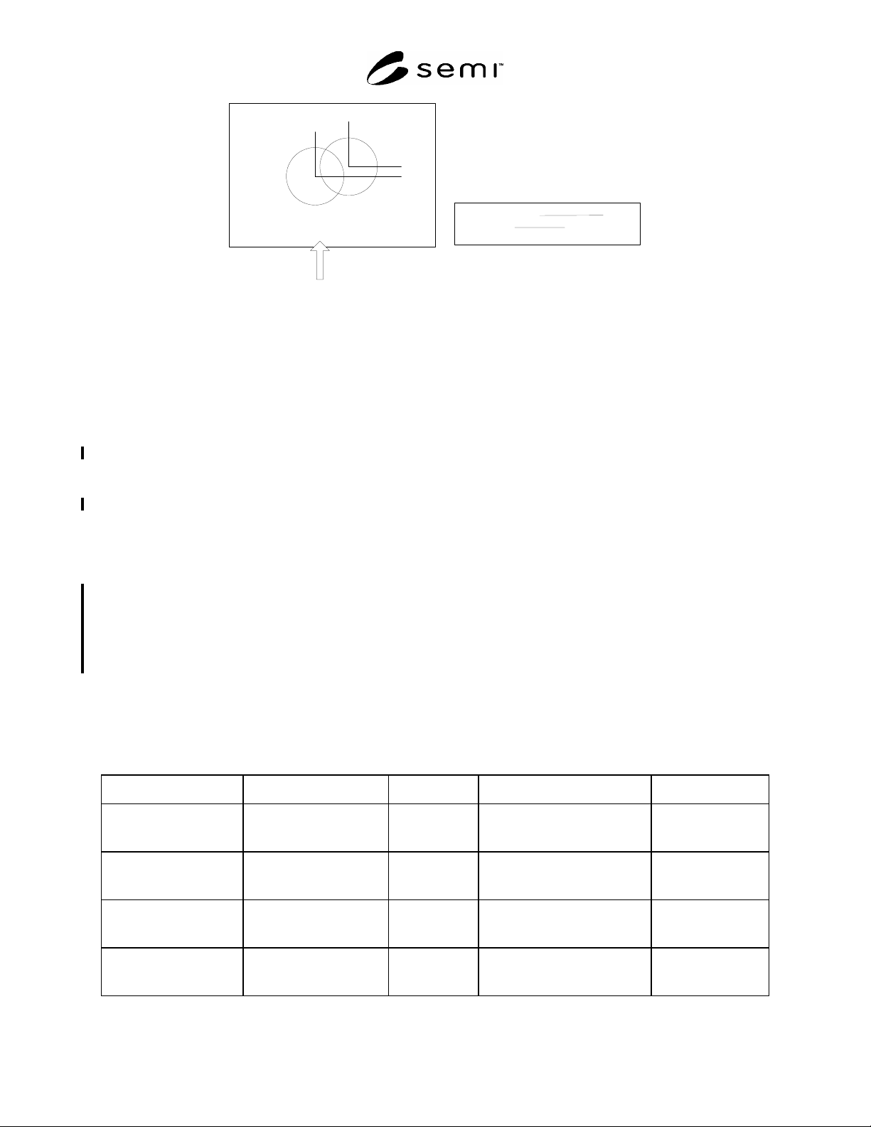
12.8.1 TransferPathCalibration for the STPO is a special service to negotiate adjustments in the arm of the robot of
the Control Client. If the STPO has sensors that can detect the (x,y,z) location of the center of the substrate as it
enters into the STPO, it reports any differences in (x,y,z) in the TransferPathCalibration service response. Through
a series of TransferPathCalibration requests and response, the robot can make adjustments until it is able to place the
substrate into the correct location. Figure 7 illustrates how the differences are calculated.
SEMI E127-0705 © SEMI 2003, 2005 24
original
location
Substrate Transfer Path
Robot
handoff
new
location
y (>0)
x (>0)
Robot handoff (into page)
original location
new location
z (>0)
Figure 7
Illustration of (X,Y,Z) Calculations
12.9 Substrate Transfer Path Events, Errors, and Alarms
12.9.1 Hardware failures shall be reported as alarms.
12.9.2 Each transition of the STPO State Model (STPSM) defined in Table 6 represents a required reportable event.
12.9.3 For implementations with an available Substrate ID Reader, there are 2 additional events and one alarm:
The SubstIDRead event occurs when the ID of an incoming substrate is read, successfully or not.
An Unexpected ID error event and an Unexpected ID alarm occur when substrate verification fails.
12.9.4 For implementations able to determine Substrate Orientation, an OrientationError error message is triggered
whenever the orientation of a substrate being loaded is different from the expected orientation provided in the
OrientationIn attribute of the substrate.
12.9.5 A Missing Substrate alarm occurs whenever a substrate previously present within the STPO can no longer be
detected. This can occur either because the substrate is broken or because of sensor failure In some cases, it may be
possible for a maintenance technician to verify that the substrate is present and undamaged, and the failure is due to
sensor failure to override this alarm. Otherwise, loading and unloading of substrates is prohibited until maintenance
has been performed to remove the broken substrate. The IMM Service state is set to OUT OF SERVICE, and the
IMM EPT state is set to BLOCKED.
12.10 Substrate Transfer Path Event Variables
12.10.1 Table 9 shows the variables that are required for STPO events. These variables are valid only at the time of
the event with which they are associated.
Table 9 Event Variables for Substrate Transfer Path Object
Variable Name Description Type Event Comment
DateTime The date and time that the
event occurred.
Conforms to the
clock format in
SEMI E98.
All.
SubstrXfrPathID Object ID of STPO. Text. All transitions of Substrate
Transfer Path Object State
Model (STPOSM).
Not required if only
one path exists.
SubstrateList Current list of substrate
IDs for substrates in the
transfer path.
List of 0+ text. All transitions of Substrate
Transfer Path Object State
Model (STPOSM).
Empty if no
Substrates are in the
transfer path.
SubstIDRead The value of the substrate
ID as read.
Text. SubstIDRead,
UnexpectedSubstrate.
Required if a
Substrate ID Reader
is available.

SEMI E127-0705 © SEMI 2003, 2005 25
Variable Name Description Type Event Comment
OrientationIn The value provided by the
Control Client.
Floating point. OrientationError. Required if the
Orientation capability
is implemented.
Orientation The actual orientation, as
determined by the STPO,
for an incoming substrate.
Floating point. OrientationError. Required if the
Orientation capability
is implemented.
#1
The SubstIDRead variable is in addition to the SubstIDRead attribute in the STPO, Substrate, and DataTable Objects. In this case, it is based
on SubstIDRead attribute of the STPO Object that generated the event.
12.11 Substrate Transfer Path Scenarios
12.11.1 This section provides examples of representative load and unload sequence to illustrate a typical sequence
of messages and actions. Related requirements are indicated.
12.11.2 Load Scenario With No Errors
12.11.2.1 Overview — The Load Scenario in Table 10 illustrates a typical flow of messages related to loading a
substrate. Other messages may occur between the Control Client and the IMM objects that are not related.
12.11.2.2 Assumptions — The following assumptions about the status of the IMM and the STPO at the start of this
scenario:
The IMM has completed its system initialization and is in the IN SERVICE state,
The Control Client has been established and is in control of the substrate handler,
The Substrate Location where the Substrate is to be loaded is in the UNOCCUPIED state,
The STPO is in the READY TO LOAD state, and
The ObjID of the STPO object is “STPO1”.
12.11.2.3 Requirements — The following requirements for loading are illustrated in Table 10.
All services listed in Table 8 except for TransferPathCalibration,
Support for micro command “Confirm Presence”, and
Support for state model and events associated with state model transitions.
12.11.2.4 Message Flow — Table 10 shows an example of the typical flow of messages used to load a substrate into
the IMM. Parameter values are examples only. Note that any particular STPO can only load one substrate at a time.
Table 10 Substrate Transfer Path Load Scenario
Comments Control Client (CC) Msg Dir STPO Comments
1 The CC must obtain this
list in order to load a
substrate into the IMM.
Typically it is one of the
first thing following the
establishment of the
control client and status
synchronization.
XfrCmdList-Request.req
Required field. XfrType = “Load”
XfrCmdList-Request.req
List of transfer commands shall
always include, at a minimum, the
command “Confirm Presence”.
Required.