semi合集-English.pdf - 第4822页
SEMI C60-0305 © SEMI 2005 7 9.7.1 Detection Limit — 1.0 ppm (vol/vol). 9.7.2 Flow Requirements — Follow t he flow requirement s specified in the manufacture r’s instrument operation manual. 9.7.3 Calibration S tandards —…

SEMI C60-0305 © SEMI 2005 6
9.5.2.2 Carrier Flow: 50 mL/min helium.
9.5.2.3 Sample Volume: 1.0 to 3.0 mL.
9.5.2.4 Temperatures:
Detector 125°C
Column Temperature 65°C
9.5.3 Calibration Standards — 5–20 ppm (mol/mol) nitrogen in helium and 1–5 ppm (mol/mol) oxygen in helium.
9.5.4 Operating Procedure
9.5.4.1 Inject the calibration standard into the column using a gas sampling valve. Record the retention time and
peak area.
9.5.4.2 Inject the sample to be tested in same manner as the calibration standard. Record the retention times and
peak areas.
9.5.4.3 Repeat ¶9.5.4.1.
9.5.4.4 Compare the average peak area of the calibration standard to that of the nitrous oxide sample being tested.
Calculate the concentrations of nitrogen and oxygen, using the formula below. The result may not exceed the
specification in Table 1 of this standard.
Sample Pea
k
Area
Standard Peak Area
Concentration
of Standard
Concentration
of Sample
9.6 Nitrogen Dioxide — This procedure is for the determination of nitrogen dioxide in nitrous oxide using an
apparatus employing a detector tube filled with a color-reactive chemical.
9.6.1 Detection Limit — 0.05 ppm.
9.6.2 Apparatus
9.6.2.1 Pressure Regulator: Outlet Pressure Range 0–30 psig.
9.6.2.2 Flowmeter: Range 0–200 mL/min.
9.6.2.3 Detector tube: Range 0.2–6 ppm.
9.6.2.4 Stop Watch.
9.6.2.5 6 mm (1/4 in) flexible tubing.
9.6.3 Operating Procedure
9.6.3.1 Attach a suitable regulator to the cylinder outlet.
9.6.3.2 Connect the flowmeter to the regulator using flexible tubing.
9.6.3.3 Open the cylinder valve and purge the flowmeter with nitrous oxide.
9.6.3.4 After the line is thoroughly purged, stop the flow of nitrous oxide and attach the detector tube to the outlet
of the flowmeter.
9.6.3.5 Start the flow of nitrous oxide and set the flow rate to 100 mL/min. The pressure and temperature of the
sample must be within the tolerance specified by the manufacturer.
9.6.3.6 Pass 800 mL of gas through the detector tube.
9.6.3.7 Determine the concentration of nitrogen dioxide according to the detector tube manufacturer's instructions.
The concentration may not exceed the specification in Table 1 of this standard.
9.7 Water — This procedure is for the determination of trace moisture (water) in nitrous oxide using a
piezoelectronic hygrometer.

SEMI C60-0305 © SEMI 2005 7
9.7.1 Detection Limit — 1.0 ppm (vol/vol).
9.7.2 Flow Requirements — Follow the flow requirements specified in the manufacturer’s instrument operation
manual.
9.7.3 Calibration Standards — Construct a calibration curve which contains at least three points covering the range
of interest. The standards employed will be verified independently by another analytical method.
NOTE 4: Other hygrometers may also be used, e.g. CRDS, FTIR, TDLAS, and vibrating quartz.
9.7.4 Sample System and Proper Operation
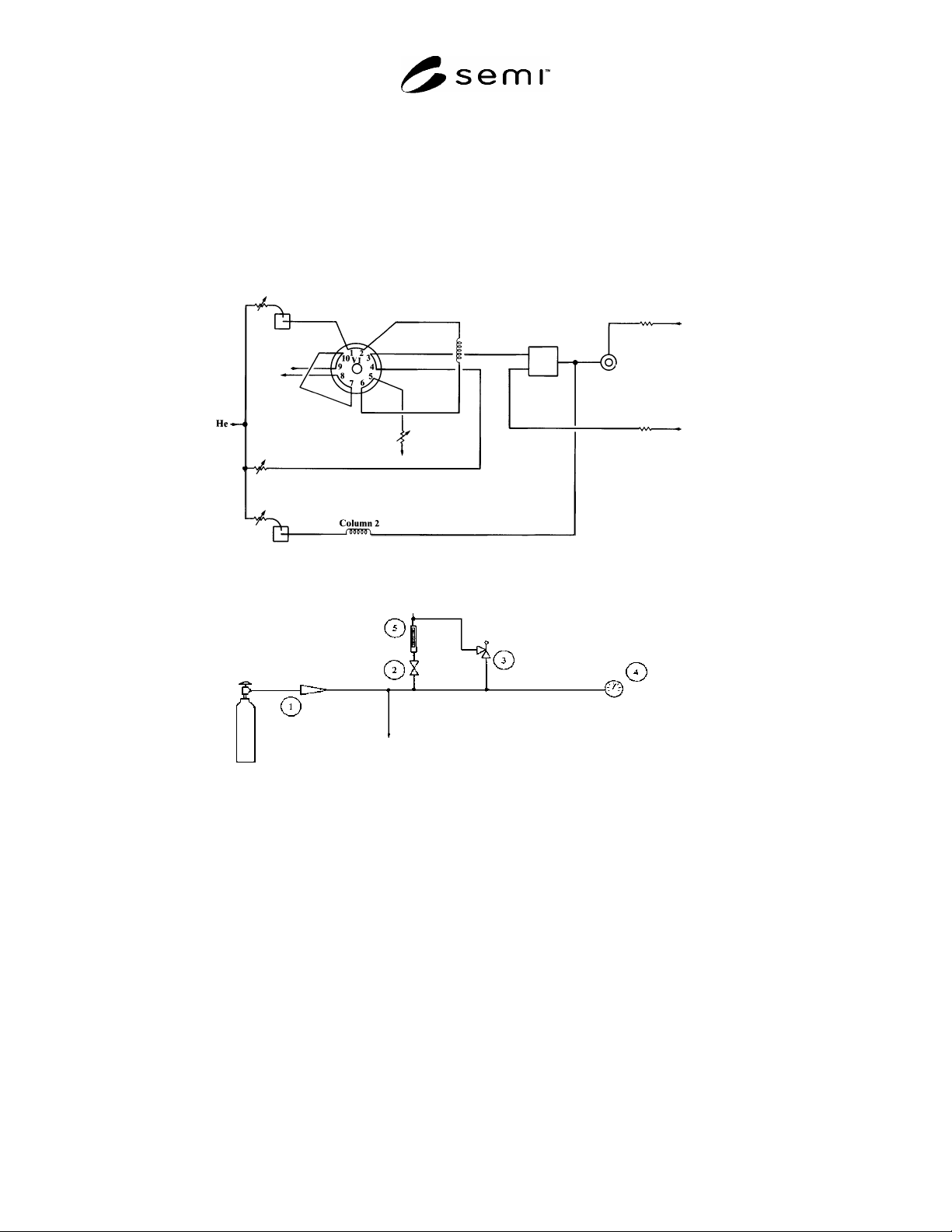
9.7.4.1 The sample system shall be as shown in Figure A1-2.
9.7.4.2 Attach sample system to nitrous oxide cylinder.
9.7.4.3 Partially open valve 2.
9.7.4.4 Open valve 1 and adjust pressure to 50 psig, ± 5 psig.
9.7.4.5 Adjust valve 2 until a flow of 500 mL/min, ± 50 mL/min is venting.
9.7.4.6 Tubing, valves and fittings are to be cleaned and passivated 316 stainless steel.
9.7.4.7 Keep tubing lengths to a minimum.
9.7.5 Operating Procedure
9.7.5.1 Follow the procedures outlined in the instrument manufacturer’s manual.
9.7.5.2 Allow the system to run until a stable reading is obtained for ten minutes.
9.7.5.3 Read the quantity of water on the analyzer meter. The result may not exceed the specification in Table 1 of
this standard.
SEMI C60-0305 © SEMI 2005 8
APPENDIX 1
GENERAL ANALYTICAL PRACTICES
NOTICE: The material in this appendix is an official part of SEMI C59 and was approved by full letter ballot procedures on
December 10, 2004 by the North American Regional Standards Committee.
A1-1 Introduce the calibration standard as many times as necessary to achieve the desired precision.
A1-2 All the gases used in the analysis of the sample should not contain more than 10% of the specified value at
the component of interest, unless otherwise specified.
Back Flush Vent
Sample
Vent
Column 1
Methanizer
A
B
FID
Figure A1-1
Valving Arrangement
N O
2
To Analyzer
1. Pressure Reducer
(316SS) heat traced to
approximately 100°F.
2. Needle valve heat
traced to 100°F.
3. Relief valve (100 psig)
reseatable.
4. Pressure gauge
(0-100 psig).
5
. Fl
o
wm
ete
r.
Figure A1-2
Nitrous Oxide Cylinder Sample System
NOTICE: SEMI makes no warranties or representations as to the suitability of the standards set forth herein for any
particular application. The determination of the suitability of the standard is solely the responsibility of the user.
Users are cautioned to refer to manufacturer's instructions, product labels, product data sheets, and other relevant
literature, respecting any materials or equipment mentioned herein. These standards are subject to change without
notice.
By publication of this standard, Semiconductor Equipment and Materials International (SEMI) takes no position
respecting the validity of any patent rights or copyrights asserted in connection with any items mentioned in this
standard. Users of this standard are expressly advised that determination of any such patent rights or copyrights, and
the risk of infringement of such rights are entirely their own responsibility.
Copyright by SEMI® (Semiconductor Equipment and Materials
International), 3081 Zanker Road, San Jose, CA 95134. Reproduction of
the contents in whole or in part is forbidden without express written
consent of SEMI.