semi合集-English.pdf - 第5104页
SEMI M24-1103 © SEMI 1994, 2003 7 13.2 The wafers supplied under this specification shall be ide ntified by appropriately labeling the outside of each box or other container and each sub division thereof in whic h it may…

SEMI M24-1103 © SEMI 1994, 2003 6
polished wafer front surface instead of reference gloss
surface as described in these feat method.
11 Surface Defect Criteria
11.1 Front surface defect criteria are shown in Item 8
in attached specification tables.
11.2 Minimal Conditions or Dimensions — The
minimal conditions or dimenions for defects stated
below shall be used for determining wafer acceptability.
Anomalies smaller than these limits shall not be
considered defects.
11.2.1 area contamination — Any foreign matter on
the surface in localized areas which is revealed under
the inspection lighting conditions as discolored,
mottled, or cloudy appearance resulting from smudges,
stains, water spots, etc.
11.2.2 crack — Any anomaly conforming to the
definition and greater than 0.25 mm (0.010 inch) in
total length.
11.2.3 crow's foot — Any anomaly conforming to the
definition and greater than 0.25 mm (0.010 inch) in
total length.
11.2.4 dimple — Any smooth surface depression
greater than 3 mm in diameter.
11.2.5 edge chip and indent — Any edge anomaly,
including saw exit marks, conforming to the definition
and greater than 0.25 mm (0.010 inch) in radial depth
and peripheral length.
11.2.6 hand scribe mark — Any mark such as that
caused by a diamond scribe that is visible under diffuse
illumination.
11.2.7 haze — Haze is indicated when the image of a
narrow beam tungsten lamp filament is detectable on
the polished wafer surface. (Under some conditions,
contamination may appear as haze.)
11.2.8 orange peel — Any roughened surface
conforming to the definition that is observable under
diffuse illumination.
11.2.9 particulate contamination — Distinct particles,
resting on the surface, which are revealed under
collineated light as bright points.
11.2.10 pit — Any individually distinguishable non-
removable surface anomaly conforming to the
definition and visible when viewed under high intensity
illumination.
11.2.11 saw marks — Any surface irregularities
conforming to the definition that are observable under
diffuse illumination.
11.2.12 scratch — Any anomaly conforming to the
definition and having a length-to-width ratio greater
than 5:1.
11.2.13 slip — Any pattern of short ridges aligned
along <111> directions and visible under diffuse
illumination.
11.2.14 striations — Any helical features conforming
to the definition and visible under diffuse illumination.
11.3 Back surface defect criteria are specified in
attached specification tables.
12 Certification
12.1 Upon request of the purchaser in the contract or
order, a manufacturer’s or supplier’s certification that
the material was manufactured and tested in accordance
with this specification, together with a report of the test
results, shall be furnished at the time of shipment.
12.2 In the interest of controlling inspection costs, the
supplier and the purchaser may agree that the material
shall be certified as “capable of meeting” certain
requirements. In this context, “capable of meeting”
shall signify that the supplier is not required to perform
the appropriate tests in Section 10. However, if the
purchaser performs the test and the material fails to
meet the requirement, the material may be subject to
rejection.
13 Packing and Marking
13.1 Special packing requirements shall be subject to
agreement between the supplier and the purchaser.
Otherwise, all wafers shall be handled, inspected, and
packed in such a manner as to avoid chipping,
scratches, and contamination, and in accordance with
the best industry practices, to provide ample protection
against damage during shipment.
SEMI M24-1103 © SEMI 1994, 2003 7
13.2 The wafers supplied under this specification shall be identified by appropriately labeling the outside of each
box or other container and each subdivision thereof in which it may reasonably be expected that the wafers will be
stored prior to further processing. Iden-tification shall include, as a minimum, wafer classifi-cation, nominal
diameter, surface orientation, growth method, lot number, and origin. In addition, identifi-cation of premium wafers
shall include conductivity type and resistivity range of the lot. The lot number, either (1) assigned by the original
manufacturer of the wafer, or (2) assigned subsequent to wafer manufacture but providing reference to the original
lot number, shall provide easy access to information concerning the fabrication history of the particular wafers in
that lot. Such information shall be retained on file at the vendor's facility for at least one month after that particular
lot has been accepted by the purchaser.
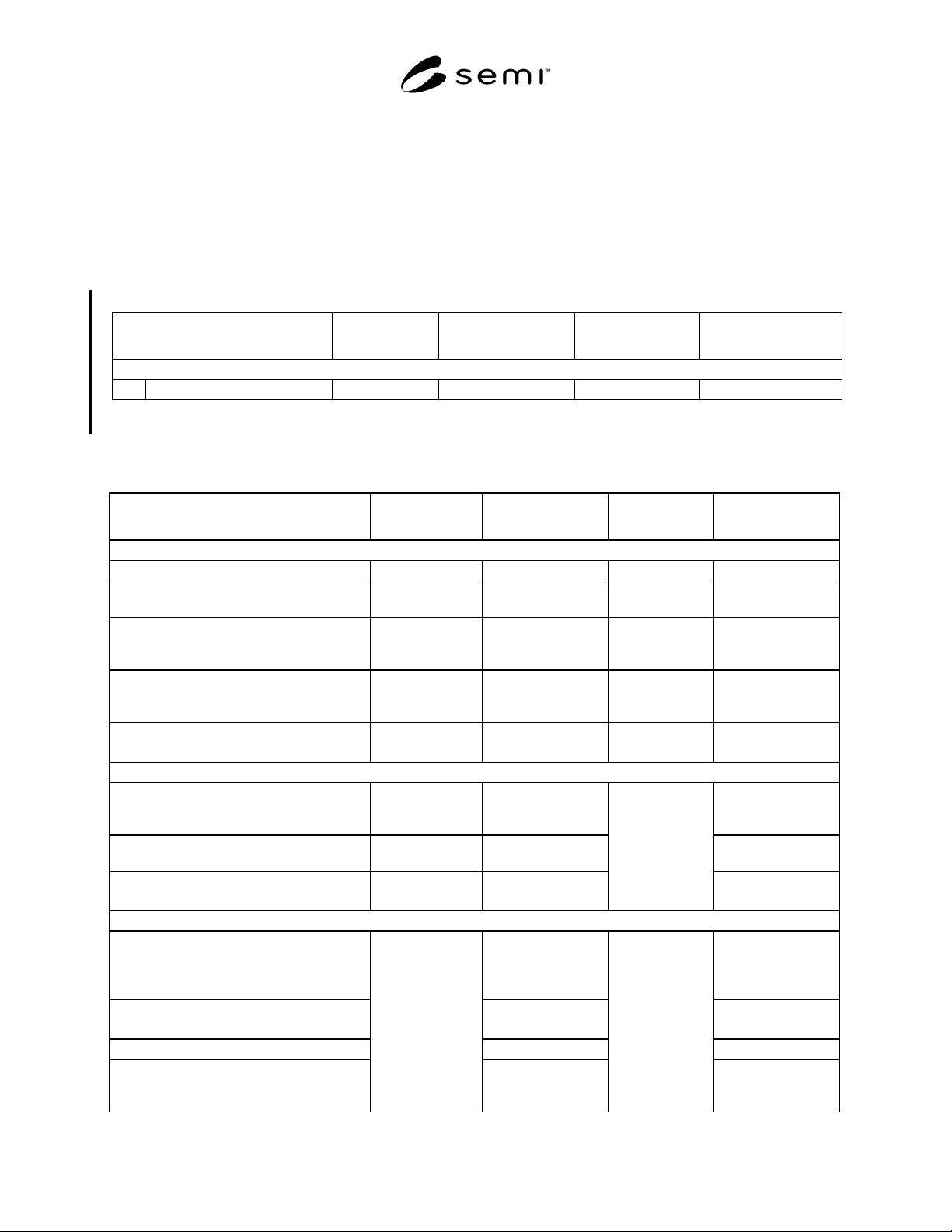
Table 2 Specification for Polished Monocrystaline Silicon Premium Wafers for 250 nm Design Rule Usage
CLASSIFICATION ITEMS
(SEMI M18)
Particle Counting Furnace & Thermal
Process
Lithography &
Patterning
Test Method
(The specification is deleted in SEMI M24, the original table can be referred to in SEMI M24 1999 to 2001
versions.)
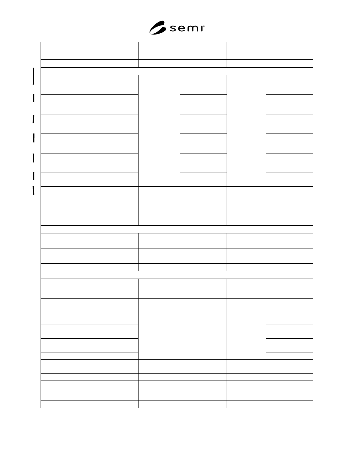
Table 3 Specification for Polished Monocrystalline Silicon Premium Wafers for 180 nm Design Rule Usage
CLASSIFICATION ITEMS (SEMI M18) Particle Counting
Furnace & Thermal
Process
Lithography &
Patterning
Test Method
1. GENERAL CHARACTERISTICS
1.1 Growth Method Cz or MCz Cz or MCz Cz or MCz
1.2. Crystal Orientation
(100) ± 1° (100) ± 1° (100) ± 1°
ASTM F 26,
DIN 50433
1.3 Conductivity Type n or p n or p n or p ASTM F 42,
JIS H607
DIN 50432
1.4 Dopant P or B P or B P or B ASTM F 1389,
F 1630, DIN
50438/3
1.5 Nominal Edge Exclusion
(Fixed Quality Area) (See Note 1.)
300 mm: 2 mm
200 mm: 3 mm
300 mm: 2 mm
200 mm: 3 mm
300 mm: 2 mm
200 mm: 3 mm
2. ELECTRICAL CHARACTERISTICS
2.1 Resistivity, Center Point NS ≥ 1 Ω-cm
(See Note 4.)
ASTM F 84, F 673,
JIS H 602,
DIN 50431, 50445
2.2 Radial Resistivity Variation NS NS ASTM F 81,
DIN 50435
2.4 Minority Carrier Lifetime
(Carrier Recombination Lifetime)
NS ≥ 325 µs
(See Note 4.)
NS
JEIDA 53, F 1535
3. CHEMICAL CHARACTERISTICS
3.1 Oxygen Concentration:
Spec. Range of Center Point: Target
≤ 1.2 × 10
18
/cm
3
ASTM F 1188,
F 1619
DIN 50438/1,
JEIDA 61
3.1.1 Oxygen Concentration:
Tolerance Around Center Point: Target
≤ 10%
3.2 Radial Oxygen Variation NS
3.3 Carbon Concentration
NS
≤ 0.2 ppma
NS
ASTM F 1391,
DIN 50438/2,
JEIDA 56
SEMI M24-1103 © SEMI 1994, 2003 8
CLASSIFICATION ITEMS (SEMI M18) Particle Counting
Furnace & Thermal
Process
Lithography &
Patterning
Test Method
3.- Total Bulk Iron Concentration
≤ 5 × 10
10
/cm
3
ASTM F 978
4. STRUCTURAL CHARACTERISTICS (See Note 9.)
4.1 Dislocation Etch Pit Density ≤ 500/cm
2
ASTM F 1725,
JIS H 609,
DIN 50434, 50443/1
4.2 Slip None ASTM F 1725
JIS H 609, DIN
50434, 50443/1
4.3 Lineage None ASTM F 1725,
JIS H 609, DIN
50434, 50443/1
4.4 Twin None ASTM F 1725,
JIS H 609, DIN
50434, 50443/1
4.5 Swirl None ASTM F 1726,
JIS H 614,
DIN 50443/1
4.6 S-pits
NS
None
NS
ASTM F 1726,
F 1049
4.7 Oxidation Induced Stacking Faults (OSF) User/Vendor ASTM F 1726,
User/Vendor mutual
agreement
4.8 Oxide Precipitates (BMD)
Interstitial Oxygen Reduction (∆ Oi)
User/Vendor
ASTM F 1239,
User/Vendor mutual
agreement
5.WAFER PREPARATION CHARACTERISTICS
5.1 Wafer ID Marking (See Note 2.) Optional Optional Optional
5.3 Denuded Zone NS NS NS
5.4 Extrinsic Gettering Treatment None None None
5.5 Backseal NS None NS
5.6 Annealing NS Donor Annih. Only NS
6. MECHANICAL CHARACTERISTCS
6.1 Diameter 200 and 300 mm 200 and 300 mm 200 and 300 mm ASTM F 613,
DIN 50441/4,
JEIDA27
6.2 Primary Flat Length/Diameter
Notch Dimensions
ASTM F 671,
F 1152, DIN
50441/4
JEIDA 27,
6.3 Primary Flat/
Notch Orientation
ASTM F 847
6.4 Secondary Flat Length ASTM F 671,
DIN 50441/4
6.5 Secondary Flat Location
SEMI M1 SEMI M1 SEMI M1
ASTM F 847
6.6 Edge Profile SEMI M1 SEMI M1 SEMI M1 ASTM F 928,
DIN 50441/2
6.- Edge Surface Finish Polished Polished Polished
6.7 Thickness, Center Point SEMI M1 SEMI M1 SEMI M1 ASTM F 533,
JIS H 611,
DIN 50441/1
6.- Nine-point Thickness Variation - - -