semi合集-English.pdf - 第104页
SEMI E10-0304 E © SEMI 1986, 2004 18 RELATED INFORMATION 1 MULTI-PATH CLUSTER TOOL RAM METRICS NOTICE : This rel ated infor mation is not an offici al part of SEMI E10 an d was derived from work done by t he SEMI NA Clus…
SEMI E10-0304
E
© SEMI 1986, 2004 17
p
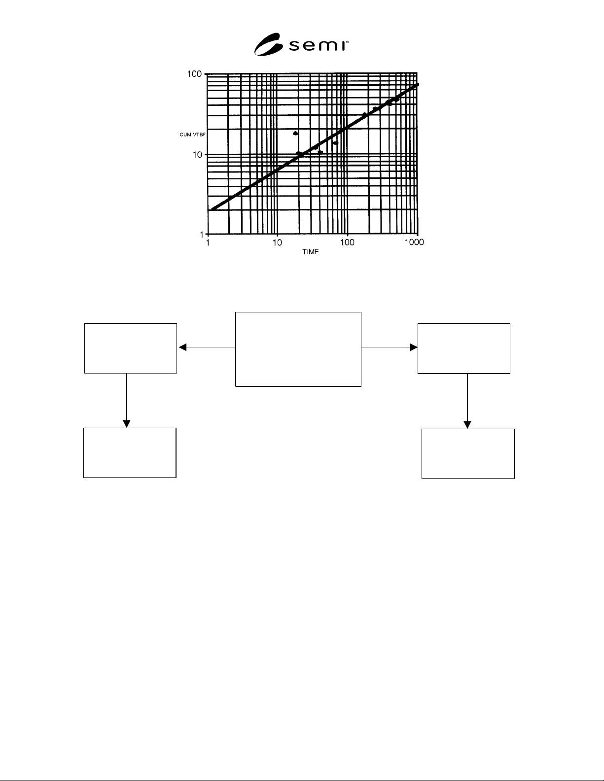
Figure A2-1
Duane Plot of CUM MTBF
p
vs. Time
Trend
N
o Trend
Sections 8.1-8.3/Appendix 2
Estimate the achieved
MTBF
p
at the end of
the period
Sections 6.2.1-6.2.2
Use standard MTBF
p
definition
Section 7.6/Appendix 1
Compute confidence
bounds for MTBF
p
Analyze the data for trends
Duane Plots
Trend Test
Section 8.3/Appendix 2
Fit AMSAA model
Figure A2-2
Flow Chart for Reliability Data Analysis
NOTICE: SEMI makes no warranties or representations as to the suitability of the standards set forth herein for any
particular application. The determination of the suitability of the standard is solely the responsibility of the user.
Users are cautioned to refer to manufacturer’s instructions, product labels, product data sheets, and other relevant
literature respecting any materials mentioned herein. These standards are subject to change without notice.
The user’s attention is called to the possibility that compliance with this standard may require use of copyrighted
material or of an invention covered by patent rights. By publication of this standard, SEMI takes no position
respecting the validity of any patent rights or copyrights asserted in connection with any item mentioned in this
standard. Users of this standard are expressly advised that determination of any such patent rights or copyrights, and
the risk of infringement of such rights, are entirely their own responsibility.

SEMI E10-0304
E
© SEMI 1986, 2004 18
RELATED INFORMATION 1
MULTI-PATH CLUSTER TOOL RAM METRICS
NOTICE: This related information is not an official part of SEMI E10 and was derived from work done by the
SEMI NA Cluster Tool RAM Metrics Task Force. This related information was approved for publication by full
letter ballot on October 15, 2003.
R1-1 Introduction
R1-1.1 This related information presents tracking
requirements and standard metrics for evaluating multi-
path cluster tool reliability, availability, and
maintainability (RAM) performance. The metrics in
the main body of SEMI E10 apply to non-cluster or
single-path cluster tools and individual modules in a
straightforward manner. While these entities are either
entirely “up” (i.e., in one of the SEMI E10 uptime
states) or entirely “down” (i.e., in one of the SEMI E10
downtime states), multi-path cluster tools may still be
capable of processing with some modules in an
unscheduled downtime state. Furthermore, the effect of
module unscheduled downtime on multi-path cluster
tool performance depends on the specific multi-path
cluster tool configuration and the combination of
modules in an unscheduled downtime state at each
point in time.
R1-1.2 Because module performance provides a
sufficient lowest common denominator for evaluating
multi-path cluster tool performance, all metrics in this
related information are calculated as functions of
module-level data only. Specific module tracking
requirements are presented. The metrics, Total Failure
Rate (TFR) and Cluster-Tool Mean Time to Repair
(MTTR
CT
), provide simple evaluations of aggregate
module reliability and maintainability.
R1-1.3 Other metrics are based on the specific
combinations of modules and process paths, defined
here as process flows.
R1-1.3.1 A process path is a specific set of modules
for which each module is unique and has no alternative
modules.
R1-1.3.2 A process flow is a defined set of modules
that is used to achieve a process, where any multi-path
cluster tool may have one or more such process flows.
A process flow may include alternative modules at one
or more steps of the process. A process flow may
therefore contain one or many process paths.
R1-1.4 A method of temporal mapping, defined in this
related information, is used to generate a history of
process flow and multi-path cluster tool states from
individual module states. Multi-path cluster tool
availability is then evaluated as the aggregate process
flow availability. Multi-path cluster tool reliability is
evaluated as the expected, or mean, productive time
between all process flows being in unscheduled
downtime.
R1-2 Module Tracking Requirements
R1-2.1 Multi-path cluster tool metrics require the
tracking of SEMI E10 state data from all of the modules
that impact the RAM or productivity of a multi-path
cluster tool or its process flows. This set of modules
includes processing and non-processing modules.
R1-2.1.1 processing module — an indivisible
production entity within an equipment system, e.g., a
processing chamber or station within a cluster tool.
(SEMI E79)
R1-2.1.2 non-processing module — an equipment
entity that supports the movement or conditioning of
units through the system, such as, robotic handler,
load/unload lock, pre-aligner.
R1-2.2 Multi-path cluster tool metrics require tracking
at the module level of at least productive states,
unscheduled downtime states, scheduled downtime
states, and other neutral states that are not in the first
three categories. Tracking of these states at the level of
the multi-path cluster tool as a whole is insufficient for
accurate evaluation of performance. Specific
requirements for tracking these states at the module
level, as well as requirements for handling the other
SEMI E10 states, are presented here.
R1-2.2.1 Productive state shall be tracked for each
module. For process modules, the productive time shall
include time for active loading and unloading of the
process module. Waiting times or inactive times,
including waiting for load, waiting for unload, and
process suspend times shall be specifically excluded
from productive time. Times for heating, cooling,
purging, cleaning, etc., that are specified as part of
process recipes shall be tracked as productive time.
However, similar times that are not specified as part of
process recipes shall be specifically excluded from
productive time.
NOTE 1: Productive state events may be derived from SEMI
E58 (ARAMS) state change data or the SEMI E116 (EPT)
module BUSY state events where the module or whole multi-
path cluster tool is known to be in a “manufacturing” state
and the SEMI E116 task type is either “Process” or
“Support.”

SEMI E10-0304
E
© SEMI 1986, 2004 19
R1-2.2.2 Unscheduled downtime state shall be tracked
for each module. Tracking of unscheduled downtime
state for the multi-path cluster tool as a whole is not
sufficient. A module cannot be in productive and
unscheduled downtime states at the same time. Each
contiguous instance of unscheduled downtime state for
a module is a module failure. Subsequent substate
events within the same instance of unscheduled
downtime state shall not to be counted as additional
failures.
R1-2.2.3 Scheduled downtime state shall be tracked for
each module. Tracking of scheduled downtime state
for the multi-path cluster tool as a whole is not
sufficient. A module cannot be in productive and
scheduled downtime states at the same time. Instances
of scheduled downtime shall not to be counted as
failures.
R1-2.2.4 Time in standby and engineering states shall
not be considered as either productive time, scheduled
downtime, or unscheduled downtime at the module
level. For the purpose of tracking multi-path cluster
tool states and calculating multi-path cluster tool and
process flow metrics, modules in these states are
considered as being in a neutral state.
R1-2.2.5 Non-scheduled time that is tracked for the
multi-path cluster tool as a whole is omitted from
operations time in calculating multi-path cluster tool
and process flow RAM metrics, as it is with the other
SEMI E10 metrics from the main body of the
specification. Non-scheduled time that is allocated to
some modules but not other modules, if any, shall be
handled differently, as follows.
R1-2.2.5.1 For new modules under installation that
have not yet been used for their intended function, those
modules shall be considered as non-existent in the
cluster-tool configuration.
R1-2.2.5.2 For installed modules that have been used,
non-scheduled time state shall be treated as a neutral
state.
R1-2.3 To calculate these metrics, an observation
period shall be defined and agreed upon by the user
and/or the supplier. Section A1-1.3 provides some
guidance on establishing the observation period time
needed to demonstrate a desired MTBF
p
at a given
confidence level.
R1-2.3.1 observation period time — elapsed calendar
time (e.g., weeks, months, quarters) observing and
tracking tool performance. No allowance is made for
the number of modules in a cluster tool.
R1-3 Total Failure Rate and Cluster-Tool Mean
Time to Repair
R1-3.1 Total Failure Rate (TFR) — total count of
module-level failure onsets, tracked according to the
requirements in Section R1-2, divided by the
observation period time. This metric characterizes the
frequency of repairs where failures on separate modules
are presumed to require independent repair actions.
TFR is an indicator of reliability and maintainability.
TFR is defined as:
TFR =
Σ
all modules
count of module failure onset events
observation
p
eriod time
NOTE 2: For different multi-path cluster tools with
comparable module failure rates, a multi-path cluster tool
with fewer modules is expected to have better performance
according to this metric than one with more modules.
However, the multi-path cluster tool with more modules may
have a better aggregate intended process flow uptime
(Uptime
CT-IPF
), as defined in Section R1-7.3.
R1-3.2 Cluster-Tool Mean Time to Repair (MTTR
CT
)
— mean time to correct a module-level failure and
return the module to a condition where it can perform
its intended function; the sum of all repair time on all
modules (elapsed module time, not necessarily total
work-hours) incurred during a specified observation
period time (including equipment and process test time,
but not including maintenance delay downtime),
divided by the total number of failure onset events
during that period.
M
TTR
C
T
=
Σ
all modules
repair time
Σ
all modules
count of module failure onset events
NOTE 3: This is the same equation as MTTR for non-cluster
and single-path cluster tools. However, because a multi-path
cluster-tool may have repairs occurring simultaneously, the
sum of repair time is not constrained to the duration of the
observation period.
R1-3.3 For any module, a failure onset event is the first
chronological event of a contiguous instance of
unscheduled downtime. To ensure that over multiple
observation periods, neither failure onset events nor
repair time is ever double-counted, the following rules
shall be followed.
R1-3.3.1 Failure onset events that occur during the
observation period are counted in TFR and MTTR
CT
regardless of when those failures are resolved.
R1-3.3.2 Failure onset events that occur before the
observation period are not counted in TFR and
MTTR
CT
, even if those failures are not resolved until
during or after the observation period.