semi合集-English.pdf - 第6056页
SEMI G6-89 © SEMI 1 983, 199 6 2 NOTICE: T hese standards do n ot purport to address safety issues, if any, ass o ciated with their use. It is the responsibility of t he user of these standards to establish appropriate s…
SEMI G6-89 © SEMI 1983, 19961
SEMI G6-89
TEST METHOD FOR SEAL RING FLATNESS
1 Purpose
This specification covers the method for determining
the maximum deviation between the seal ring and a
reference plane defined by three fixed points on the seal
ring. This method will not work on parts smaller than
0.330" × 0.330".
2 Equipment
2.1 Flat plate (black granite calibrated at ± 0.000025"
(± 0.000835 mm) or equivalent).
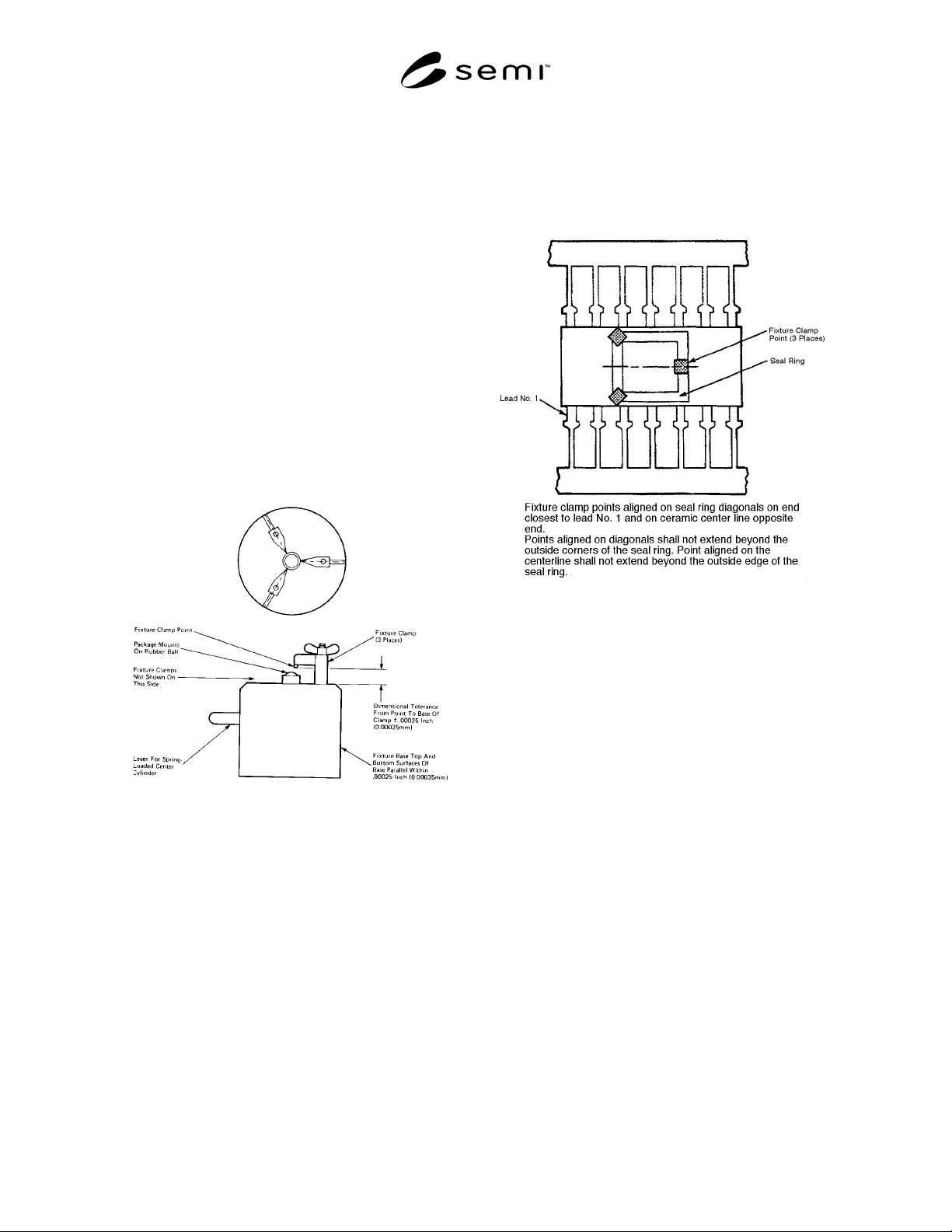
2.2 Fixture Clamps — Three required (See Figure 1).
2.3 Fixture Base — (See Figure 1).
2.4 Test Indicator — (Hamilton Kwik Check or
equivalent).
Figure 1
Fixture Base and Clamp Assembly
3 Preparation
3.1 Fixture clamps shall be adjusted for part to be
measured (see Figure 2).
3.2 The gaging fixture is to be calibrated with a
precision ground gage block before each sample is
measured.
3.2.1 Place gage block under the three fixture clamp
points and release center cylinder to hold in place.
3.2.2 Position fixture base so the point of the test
indicator is on the gage block.
3.2.3 Move fixture base so the point of the test
indicator traverses the entire surface of the gage block.
The total deviation read on the test indicator shall not
exceed 0.0005" (0.013 mm).
Figure 2
Fixture Clamp Orientation
4 Procedure
4.1 Place the package under the three fixture clamp
points and release cylinder to hold in place (see Figure
2) for orientation of package seal ring and fixture clamp
points.
4.2 Position fixture base so the point of the test
indicator is on the package seal ring.
4.3 Move fixture base so the point of the test indicator
traverses the length of the seal ring.
4.3.1 Move fixture base so the point of the test
indicator stays in the middle of the seal ring.
4.3.2 Test indicator shall be relocated twice to get
around fixture points.
5 Evaluation
If material buildup on the seal ring is visible with the
unaided eye, the part shall not be used for this
measurement.

SEMI G6-89 © SEMI 1983, 1996 2
NOTICE: These standards do not purport to address
safety issues, if any, associated with their use. It is the
responsibility of the user of these standards to establish
appropriate safety and health practices and determine
the applicability of regulatory limitations prior to use.
SEMI makes no warranties or representations as to the
suitability of the standards set forth herein for any
particular application. The determination of the
suitability of the standard is solely the responsibility of
the user. Users are cautioned to refer to manufacturer’s
instructions, product labels, product data sheets, and
other relevant literature respecting any materials
mentioned herein. These standards are subject to
change without notice.
The user’s attention is called to the possibility that
compliance with this standard may require use of
copyrighted material or of an invention covered by
patent rights. By publication of this standard, SEMI
takes no position respecting the validity of any patent
rights or copyrights asserted in connection with any
item mentioned in this standard. Users of this standard
are expressly advised that determination of any such
patent rights or copyrights, and the risk of infringement
of such rights, are entirely their own responsibility.
Copyright by SEMI® (Semiconductor Equipment and Materials
International), 3081 Zanker Road, San Jose, CA 95134. Reproduction o
f
the contents in whole or in part is forbidden without express written
consent of SEMI.

SEMI G8-94 © SEMI 1983, 19961
SEMI G8-94
TEST METHOD FOR GOLD PLATING
1 Preface
1.1 Purpose — This test method describes procedures
to determine gold plating quality.
1.2 Scope — These methods apply to gold plating on
cofired ceramic or metal packages. The grade, hardness,
and thickness of the gold plating shall be specified per
MIL-G-45204 unless otherwise agreed between vendor
and customer.
Note 1: The gold plate may be over refractory metal on
cofired ceramic packages or over an underplate on metal
packages.
2 Applicable Documents
2.1 Referenced Documents
2.1.1 SEMI Specifications — All SEMI package
specifications
2.1.2 ASTM Specifications
1
B 384 — Standard Test Method for Microhardness of
Materials
B 487 — Test Method for Measurement of Metal and
Oxide Coating Thicknesses by Microscopic
Examination of a Cross-Section
B 567 — Method for Measurement of Coating
Thickness by the Beta Backscatter Method
B 568 — Method for Measuring Coating Thickness by
X-Ray Spectrometry
F 1269 — Test Methods for Destructive Shear Testing
of Ball Bonds
2.1.3 Military and Federal Specifications
2
MIL-STD-750 — Test Methods for Semiconductor
Devices
MIL-STD-883 — Test Methods and Procedures for
Microelectronics
MIL-G-45204 — Gold Plating, Electrodeposited
2.2 Related Documents
Military and Federal Specifications
MIL-STD-105 — Sampling Procedures and Tables for
Inspection by Attributes
1 American Society for Testing and Materials, 100 Barr Harbor
Drive, West Conshohoken, PA 19428-2959
2 Military Standards, Naval Publications and Form Center, 5801
Tabor Avenue, Philadepphia, PA 19120
MIL-STD-202 — Test Methods for Electronic and
Electrical Componenet Parts
MIL-STD-19500 — General Specification for
Semicondutor Devices
MIL-M-38510 — General Specification for
Microcircuits
3 Summary of Method
Various test methods are described or referenced to
determine gold plating quality for the following items:
Visual Appearance
Plating Thickness
Plating Adhesion
Functional tests
Salt Atmosphere
Hardness
4 Significance and Use
4.1 Significance — Poorly plated components result in
lowered yields during package assembly operations or
to reliability problems.
4.2 Use — The methods described in this document
may be used by vendors to test gold plated components
as part of their process control program, or by
customers at incoming inspections.
The methods are to used in conjunction with individual
component specifications.
5 Terminology
5.1 blister (metal) — An enclosed, localized
separation of a metallization layer from its base
material (such as ceramic or another metal layer) that
does not expose the underlying layer.
5.2 discoloration — The change in color of any plated
metallization, gold, silver, aluminum, etc., as detected
by the unaided eye after the application of heat to the
metallization. The metallization may be over base
metal, another plated layer, or on refractory metal.
5.3 peeling (flaking) — Any separation of the plated,
vacuum deposited or clad metal from the base metal of
a leadframe, lead, pin, heatsink, or seal ring, from an
underplate, or from refractory metal on a ceramic
package. Peeling exposes the underlying material. Also
called flaking.