semi合集-English.pdf - 第4739页
SEMI C3.52-02 00 © SEMI 1995 , 2000 3 by Inductively C o upled Plasma Mass Spectrometry (ICPMS). 6.4.1 Detect ion Lim its (ppb w t/wt) — C a : 1.5; Co: 0.1; Cr: 0.8, Cu : 0.5; Fe: 1; K: 1.5; Mg: 0.1, Mn : 0.1, Mo: 0.5; N…
SEMI C3.52-0200 © SEMI 1995, 2000 2
10 ppm silicon tetrafluoride in helium or permeation
device (see Figure 3).
6.1.3 Operating Procedure
6.1.3.1 Attach a suitable pressure regulator to the
standard cylinders. Connect the regulator to the
dedicated WF
6
handling system which is connected to
the chromatographic sampling valve.
6.1.3.2 Purge the sampling lines with the standard for
at least one minute.
6.1.3.3 Inject the standard into the gas chromatograph.
Record the retention times and peak areas. Order of
elution for the above mentioned standard is carbon
tetrafluoride, silicon tetrafluoride, carbon dioxide, and
sulfur hexafluoride.
6.1.3.4 Inject the WF
6
sample to be analyzed in the
same manner as the calibration standard. Record the
retention times and peak areas.
6.1.3.5 Compare the average peak areas of the
calibration standard to that of the detected peak in
tungsten hexafluoride. Calculate the concentration of
each impurity using the standard and sample peak areas
and the standard concentration. The results may not
exceed the specifications.
6.2 Oxygen and Argon, Nitrogen, and Carbon
Monoxide — This procedure is for the determination of
oxygen and argon, nitrogen, and carbon monoxide in
tungsten hexafluoride using a gas chromatograph
equipped with a helium ionization detector. A backflush
is used in order to protect the detector from the main
component.
6.2.1 Detection Limits
6.2.2 Instrument Parameters
6.2.2.1 Columns:
Column 1: 10% Kel F Nr 10 on Chromosorb T, 4.0 m (13 ft)
by 3.2 mm (1/8 in) nickel or equivalent.
Column 2: Preconditioned HAYESEP Q, 60/80 mesh, 3 m
(10 ft) by 3.2 mm (1/8 in) or equivalent. The
columns should be treated by repeated WF
6
sample injections at 125°C.
Column 3: Molecular sieve 5 A, 60/80 mesh, 2 m (6 ft) by
3.2 mm (1/8 in).
6.2.2.2 Carrier Flow — 26 mL/min helium, 6.0 grade.
6.2.2.3 Temperatures:
Detector 50°C
Column Oven 50°C
6.2.2.4 Sample Volume — 2 mL
6.2.2.5 Calibration Standards — 1 and 5 ppm
(mole/mole) oxygen, nitrogen, and carbon monoxide in
helium (see Figure 4).
6.2.3 Operating Procedure
6.2.3.1 Attach a suitable pressure regulator to the
standard cylinder. Connect the regulator to the
dedicated WF
6
handling system, which is connected to
the chromatographic sampling valve.
6.2.3.2 Purge the sampling lines with the standard for
at least one minute.
6.2.3.3 Inject the standard into the gas chromatograph.
Switch the valves in order to operate in the same
conditions as the WF
6
sample analysis. Record the
retention times and peak areas. Order of elution for the
above mentioned standard is oxygen and argon,
nitrogen, and carbon monoxide.
6.2.3.4 Inject the WF
6
sample in the same manner as
the calibration standard. Record the retention times and
peak areas.
6.2.3.5 Compare the average peak areas of the
calibration standard to that of the detected peak in the
tungsten hexafluoride. Calculate the concentration of
each impurity using the standard and sample areas and
the standard concentration. The results may not exceed
the specifications.
6.3 Hydrogen Fluoride — This procedure is for the
determination of hydrogen fluoride in tungsten
hexafluoride using Fourier Transform Infra Red (FTIR)
analyzer.
6.3.1 Detection Limit — 0.5 ppm (mole/mole).
6.3.2 Instrument Parameters
• cell with CaF
2
windows
• HF band: 4038,8 cm
-1
• resolution: 2 cm
-1
• path length: 12 cm
6.3.3 Calibration Standard — Calibrate with low
vapor pressure hydrogen fluoride or permeation device.
6.3.4 Operating Procedure — Carefully dry the cell
before sampling tungsten hexafluoride. Then purge it
with tungsten hexafluoride and record the
concentration. When it is steady, that means the line is
purged and the true hydrogen fluoride concentration is
obtained.
6.4 Elemental Impurities — This procedure is for the
determination of Ca, Co, Cr, Cu, Fe, K, Mg, Mn, Mo,
Na, Ni, Pb, Th, U, and Zn in the nonvolatile residue of
liquid phases tungsten hexafluoride (WF
6
) and analyzed

SEMI C3.52-0200 © SEMI 1995, 20003
by Inductively Coupled Plasma Mass Spectrometry
(ICPMS).
6.4.1 Detection Limits (ppb wt/wt) — Ca: 1.5; Co: 0.1;
Cr: 0.8, Cu: 0.5; Fe: 1; K: 1.5; Mg: 0.1, Mn: 0.1, Mo:
0.5; Na: 0.6; Ni: 1; Pb: 0.1; Th, U: 0.01; and Zn: 0.8.
6.4.2 Sampling Apparatus — Figure 5 shows the
sampling apparatus used for obtaining a liquid phase
sample of WF
6
. The sampling apparatus consists of:
• Cylinder Inverter,
• PFA Vessels,
• PFA Valves, and
• PFA Tubing.
The whole sampling system is placed inside a hood.
6.4.3 Water — At least 18 MΩ DI water should be
used for all dilutions, blanks, and washing.
6.4.4 Reagents — All reagents are of the highest purity
available minimizing background metal contamination.
The following reagents are needed to prepare the
sample and standards:
• Aqueous Ammonia,
• Aqueous HNO
3
,
• Aqueous HF, and
• NIST traceable ICP standards.
6.4.5 Sampling Liquid Tungsten Hexafluoride
6.4.5.1 Place about 400 ml of DI water in each of the
hydrolysis vessels. Obtain the weight of each of the
hydrolysis vessels.
6.4.5.2 Assemble the apparatus as shown in Figure 1.
Do not tighten the cylinder CGA connection. All PFA
parts should be clean and dried prior to assembly.
6.4.5.3 Open valves V2, V3, V4 and V5. Set the
house nitrogen pressure to approximately 15 psig.
Purge the system with nitrogen for about 15 minutes.
TIGHTEN THE CYLINDER CGA CONNECTION.
6.4.5.4 Close V2. The system should now be under
pressure. Check for leaks and repair if necessary.
6.4.5.5 Open V1 and evacuate the system for
approximately 10 minutes.
6.4.5.6 Close all valves.
6.4.5.7 Fill sample vessel by opening cylinder valve
and valve V5. Fill the sample vessel approximately 2/3
full. Close cylinder valve.
6.4.5.8 Close V5. Open V2, V4, and V6. This will
carry the WF
6
vapors to the hydrolysis vessel.
6.4.5.9 Purge the system with nitrogen for a few
minutes after the WF
6
liquid in the sample cup has
totally evaporated.
6.4.5.10 Close all valves. Remove the hydrolysis
vessels and weigh the vessels.
6.4.5.11 The weight gain in the hydrolysis vessel will
give the weight of the sampled WF
6
. Typically the
weight gain of the second and third vessels will be less
than 1% of the weight gain of the first hydrolysis
vessel.
6.4.5.12 Remove the sample vessel and dissolve the
residue.
6.4.6 Sample Preparation
6.4.6.1 Add 20 ml DI water to a 100 ml volumetric
flask.
6.4.6.2 Open the sample cup and add 5 ml of aqueous
ammonia to the cup.
6.4.6.3 Swirl in the cup and place in a 100 ml
volumetric flask.
6.4.6.4 Add 5 ml Nitric Acid to the cup.
6.4.6.5 Swirl and place in the same 100 ml volumetric
flask.
6.4.6.6 Add 5 ml Hydrofluoric Acid to the cup.
6.4.6.7 Swirl and place in the same 100 ml volumetric
flask as before.
6.4.6.8 Dilute the solution with DI water up to the
mark of the 100 ml volumetric flask.
6.4.6.9 Analyze for metals in the sample.
6.4.7 ICPMS Analysis Procedure
6.4.7.1 This procedure is used to analyze for trace Na,
K, Cr, Fe, Th and U using multi point calibration.
Other elements can be analyzed using a single point
calibration. Elements for which stable standards can
not be obtained, can be analyzed using interpolation
and a knowledge of the instrument response function.
The ICPMS should be calibrated using matrix matched
multielement standards. At least one spiked sample
should be analyzed as part of the analytical procedure.
The recovery of the spikes should be within ± 25%. At
least three standards and a blank should be used for the
calibration. Regression based approach should be used
to calculate the response factors. The limit of detection
(LOD) should be calculated following SEMI C10,
Guide for Determination of Method Detection Limits.
SEMI C3.52-0200 © SEMI 1995, 2000 4
6.4.7.2 The concentration of impurities in gas phase
WF
6
is given by
6
6
WFSampled ofWeight
Solution of Wt.Solution in Conc.
WF in Conc.
×
=
NOTE 1: All gases used in the analysis of the sample should
contain not more than 10% of the specified value of the
component of interest unless otherwise specified.
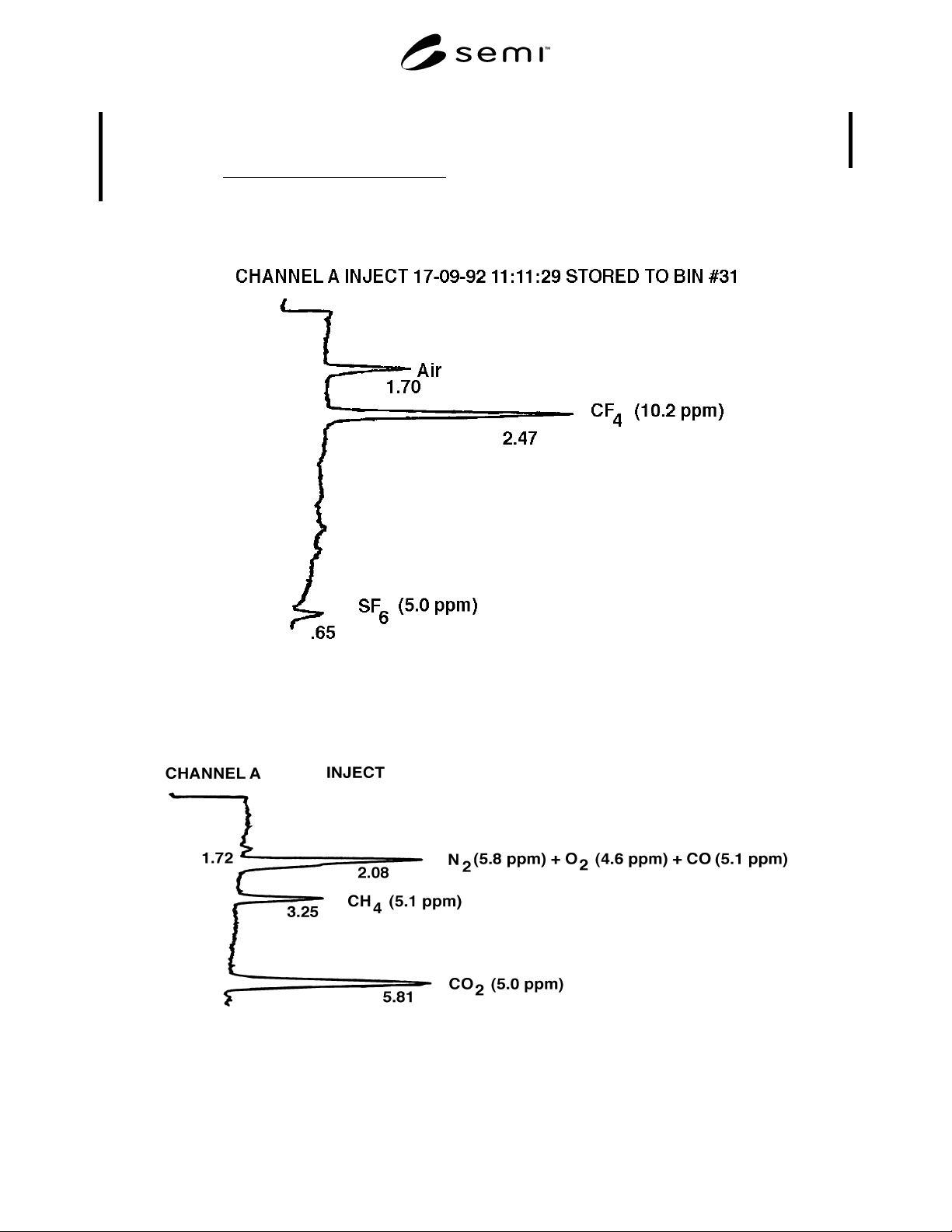
Figure 1
CF
4
and SF
6
Standards in He
Figure 2
CO
2
Standards in He