semi合集-English.pdf - 第1946页
SEMI E54.3-0698 © SEMI 1998, 2004 3 Integer(range of 1 to 31) 5.2.6 double integer (DINT) — an integer, four bytes long, in the range -2 31 to 2 31 –1. 5.2.7 enumerated byte — a by te with assigned meaning to the values …

SEMI E54.3-0698 © SEMI 1998, 2004 2
3.5 Operation over the entire range specified for an
attribute within a specific object instance is not a
requisite for compliance with this specification.
4 Referenced Standards
4.1 SEMI Standards
SEMI E12 — Standard for Standard Pressure,
Temperature, Density, and Flow Units Used in Mass
Flow Meters and Mass Flow Controllers
SEMI E18 — Guideline for Temperature Specifications
of the Mass Flow Controller
SEMI E39 — Object Services Standard: Concepts,
Behavior, and Services
SEMI E52 — Practice for Referencing Gases and Gas
Mixtures Used in Digital Mass Flow Controllers
SEMI E54.1 — Standard for Sensor/Actuator Network
Common Device Model
4.2 IEEE Document
1
IEEE 754 — Floating Point Definition
NOTICE: Unless otherwise indicated, all documents
cited shall be the latest published versions.
5 Terminology
5.1 Terminology Defined in Standard for
Sensor/Actuator Network Common Device Model
(SEMI E54.1)
5.1.1 Attribute
5.1.2 Behavior
5.1.3 Byte
5.1.4 Character
5.1.5 Device
5.1.6 Device Manager (DM) Object
5.1.7 Device Model
5.1.8 Instance
5.1.9 Nibble
5.1.10 Object
5.1.11 S, A, and C Objects
5.1.12 Sensor Actuator Controller (SAC) Object
5.1.13 Service
1 Institute of Electrical and Electronics Engineers, IEEE Operations
Center, 445 Hoes Lane, P.O. Box 1331, Piscataway, New Jersey
08855-1331, USA. Telephone: 732.981.0060; Fax: 732.981.1721,
Website: www.ieee.org
5.1.14 State Diagram
5.2 Definitions
5.2.1 boolean (BOOL) — a binary bit representing 0
and 1 corresponding to FALSE and TRUE or
DISABLE and ENABLE respectively.
5.2.2 common device model (CDM) — refers to
Sensor/Actuator Network Common Device Model
(SEMI E54.1).
5.2.3 data type — an unsigned short integer formatted
as an enumerated byte to specify attribute data format.
The intended use of this attribute type is in cases where
an attribute, or set of attributes, may be defined,
allowing for more than one level of support (e.g., INT
or REAL). The following values are defined:
0 = INT
1 = REAL
2 = USINT
3 = SINT
4 = DINT
5 = LINT
6 = UINT
7 = UDINT
8 = ULINT
9 = LREAL
10–99 = reserved for CDM
100–199 = reserved for SDMs
200–255 = manufacturer-specified
5.2.4 data units — an unsigned integer formatted as an
enumerated byte to specify attribute data units. The
intended use of this attribute type is in cases where an
attribute, or set of attributes, may be defined, allowing
for more than one unit’s context. The values are defined
in an appendix of this document.
5.2.5 date — a data structure of four bytes used to
represent a calendar date. Table 1 defines the format of
the date data type.
Table 1 Date Format
Data # Description Range
0–1 Year Unsigned Integer
2 Month Unsigned Short
Integer(range of 1 to 12)
3 Day Unsigned Short

SEMI E54.3-0698 © SEMI 1998, 2004 3
Integer(range of 1 to 31)
5.2.6 double integer (DINT) — an integer, four bytes
long, in the range -2
31
to 2
31
–1.
5.2.7 enumerated byte — a byte with assigned meaning
to the values 0 through 255. May take on one of a
limited set of possible values.
5.2.8 full scale range — the defined 100% value of an
attribute in its assigned units. This value is not
necessarily the maximum value for the attribute. As an
example, the indicated flow attribute value may attain
120% of the full scale range.
5.2.9 gas calibration — a reference to a set of
parameters or methods which are used to calibrate or
correct the device for a particular gas type, range, and
units.
5.2.10 gas standard number — a number that refer-
ences a gas type. The number and its referenced gas
type are defined in SEMI E52.
5.2.11 gas standard symbol — a text symbol that
references a gas type. The symbol and its referenced
gas type are defined in SEMI E52.
5.2.12 last valid value (LVV) — the most recent value
successfully assigned to an attribute.
5.2.13 long integer (LINT) — an integer, eight bytes
long, in the range -2
63
to 2
63
-1.
5.2.14 long real (LREAL) — a double floating point
number, eight bytes long, as defined in IEEE 754.
5.2.15 manufacturer — in the context of this docu-
ment, this refers to the manufacturer of the device.
5.2.16 mass flow controller (MFC) — a self-contained
device, consisting of a mass flow transducer, control
valve, and control and signal-processing electronics,
commonly used in the semiconductor industry to
measure and regulate the mass flow of gas.
5.2.17 mass flow device (MFD) — a device which is
either a mass flow controller or mass flow meter.
5.2.18 mass flow meter (MFM) — a self-contained
device, consisting of a mass flow transducer and sig-
nal-processing electronics, commonly used in the
semiconductor industry to measure the mass flow of
gas.
5.2.19 null character — a byte with a value of zero.
5.2.20 programmed gas calibration — a reference to a
particular gas type, range, and units for which the
device is currently calibrated.
5.2.21 real (REAL) — a floating point number, four
bytes long, as defined by IEEE 754.
5.2.22 short integer (SINT) — an integer, one byte
long, in the range -128 to 127.
5.2.23 signed integer (INT) — an integer, two bytes
long, in the range -32768 to 32767.
5.2.24 text string — a string of one-byte characters.
See Section 5.1 for a definition of a character.
5.2.25 unsigned integer (UINT) — an integer, two
bytes long, in the range 0 to 65535.
5.2.26 unsigned short integer (USINT) — an integer,
one byte long, in the range 0 to 255.
6 Requirements
6.1 In order to implement this standard in a Mass Flow
Device, it is necessary to also implement SEMI E54.1
and one of the Sensor/Actuator Network
Communication standards. See Section 2 for more
information on a complete interoperability standard.
7 Conventions
7.1 This document embraces the Harel State Chart
notation, the transition table definition format, the
object attribute representation formats, service message
definition formats, and behavior definition formats as
specified in SEMI E54.1.
7.2 Figure 1 describes the convention for object
representation used throughout this specification.
OBJECT NAME
-------------------------
Attributes
-------------------------
Services
Figure 1
Object Representation
8 Device High Level Structure
8.1 General Description — The high level object view
of a Mass Flow Meter (MFM) device and a Mass Flow
Controller (MFC) Device is shown in Figure 2.
8.1.1 Note that the “MFM” and the “MFC” objects are
depicted in Figure 2 only for the purposes of illustrat-
ing a high level view of the device and its component
objects. In the context of this document, these objects
are not addressable, do not have addressable attributes,
do not have accessible services, nor do they exhibit any
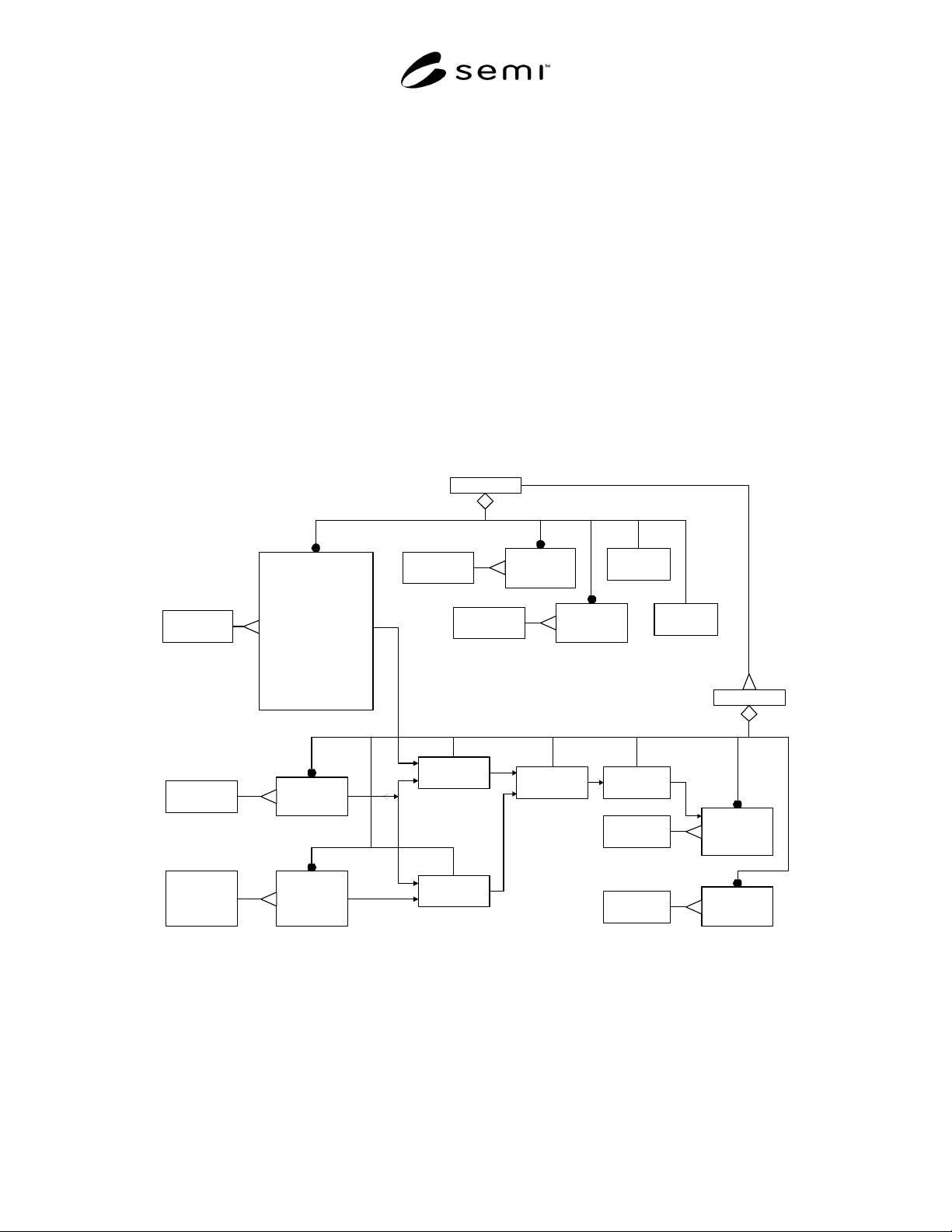
SEMI E54.3-0698 © SEMI 1998, 2004 4
defined behavior. These objects are only included in the
figures to aid in the visualization of the device.
8.1.2 This document defines in detail all of the
component objects unique to the MFC and the MFM
devices. References, rather than definitions, are
included for the DM, the SAC, and other objects
defined in SEMI E54.1.
8.1.3 Many of the objects defined in this document
inherit properties from other objects. The properties
inherited include attribute, service, and behavior
definitions. These other objects are specified here or in
SEMI E54.1.
8.1.4 This document provides for future extensions, as
well as manufacturer-specific enhancements, by
reserving object attribute identifiers and object service
identifiers. Specifically, all object definitions in this
document specify or reserve the first 64 attribute
identifiers (A1 through A64) and the first 64 service
identifiers (S1 through S64), allowing manufacturers to
specify identifiers beyond these ranges. Additionally,
byte-enumerated attributes are specified or reserved
from 0 to 63, allowing manufacturers to specify
enumerations beyond this range (64 to 255).
8.1.5 Mass Flow Meter (MFM) Device Description —
A Mass Flow Meter device profile is composed of the
component objects and object relationships shown in
Figure 2.
8.1.6 Mass Flow Controller (MFC) Device Description
— A Mass Flow Controller device profile is composed
of (1) all of the component objects and object
relationships of the Mass Flow Meter Device in
addition to (2) the component objects and object
relationships as shown in Figure 2.
SAC
(defined in CDM)
DM
(defined in CDM)
MFM Device
Controller
(defined in CDM)
Actuator-AO-MF
--------------------
ValveType
Override
Assembly-MFM
-----------------
Sensor-AI-MF
-------------------------
FlowTotalizer
FlowHours
ZeroingStatus
ZeroOffsetMode
AutoRangeStatus
-------------------------
PerformZeroOffset
AutoRange
QuerySupportedGasType
SelectProgrammedGasType
InsertGasType
DeleteGasType
GetGasCalibrationDataValue
SetGasCalibrationDataValue
MFC Device
Sensor-AI-Aux
------------------
Assembly-MFC
--------------------
SISO-Setpoint
-------------------
RampType
RampRate
Ratio
SISO
------------------
Input
Output
DataType
Sensor-AI
(defined in CDM)
Sensor-AI
(defined in CDM)
Local Link
(defined in CDM)
Local Link
(defined in CDM)
Local Link
(defined in CDM)
Actuator-AO
(defined in CDM)
Sensor-AI-AT
------------------
Sensor-AI
(defined in CDM)
Assembly
(defined in CDM)
Assembly
(defined in CDM)
Figure 2
Mass Flow Meter Device and Mass Flow Controller Device
High Level Structure