semi合集-English.pdf - 第703页
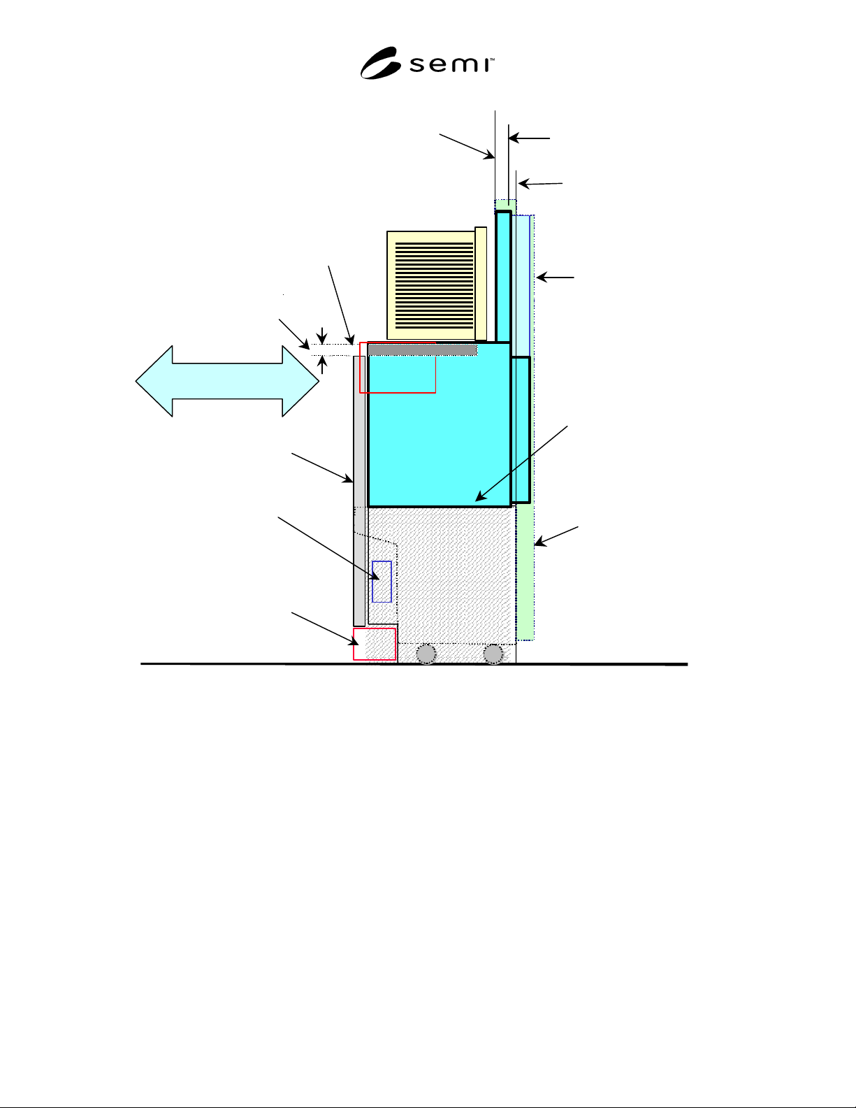
SEMI E92-0302 E © SEMI 1999, 2003 6 SEMI E15.1 Com patible Equ ipment Boundary SEMI E8 4 Forklifts exclusion volume Reduce Reserved Space Parallel I/O for AMH S Communicat ion BOLTS/M Plane BOLTS/M image (Adopter) Cart t…

SEMI E92-0302
E
© SEMI 1999, 2003 5
loading slider area should be open z112 under the
bottom interface planes.
7.4.3 Loader Locating Pins — Equipment must have
two Loader locating pins to locate the box
opener/loader so as to provide highly repeatable and
quick attachment/detachment. Horizontal locations of
the loader locating pins are defined by x106 and y106.
Height of the loader locating pins is defined by z110.
Diameter of the loader locating pins is defined by d1.
A box opener/loader compatible with this standard must
refer these two Loader Locating pins.
7.4.3.1 Positioning Pin — Loader locating pin on the
left side from operator is a positioning pin that is used
to hold box opener/loader both in x and y directions.
7.4.3.2 Anti-Rotation Pin — Loader locating pin on the
right side from operator is an anti-rotation pin that is
used to hold box opener/loader in y direction only (see
Figure 4).
7.4.4 Locking Screws — Four locking screws defined
by x106, y107, and y108 to tighten the box
opener/loader.
7.4.4.1 The equipment should have M8-16 tapped
holes at these locations.
7.4.5 Control Connection Area — Area used to pass
connectors, wires, and tubes for electrical signals,
power supply and other inlets/outlets.
7.4.5.1 The control connection area is defined at the
same height as the the bottom interface planes by x107
and y109.
NOTE 5: This standard only defines the connection area for
the box opener/loader itself. It is recommended that
connectors will be located above this area for quick
maintainability.
7.4.5.2 Other connections which will possibly be
located in this area for other functions are listed below
and may be defined in separate standards:
• Carrier ID reader/writer head interface (automated
units that read or write to an ID tag defined in
SEMI E15.1)
• Manual operation panel
• Wafer mapper
7.5 Panel Interface Height — This standard defines an
optional panel interface height so as to provide panel
installation height to enclose box opener/loader in the
equipment. Panel interface height is defined by z111
from horizontal datum plane. In case this option is
used, both equipment and the box opener/loader should
have forklifts exclusion volume defined by SEMI E15.1
H0.
SEMI E92-0302
E
© SEMI 1999, 2003 6
SEMI E15.1 Compatible Equipment
Boundary
SEMI E84
Forklifts exclusion volume
Reduce Reserved
Space
Parallel I/O for AMHS
Communication
BOLTS/M Plane
BOLTS/M image
(Adopter)
Cart to SEMI E15.1
Docking Interface Port
BOLTS/Light Plane
SEMI E15.1 Compliant Load
Port Height
Equipment panel
Slide In/Out
CIDRW
BOLTS/
Light
BOLTS/Light
Shelf
Bottom interface
plane
Figure 1
Diagram Concept of Light-Weight and Compact Box Opener/Loader and Tool-Interoperability Standard
(BOLTS/Light)
SEMI E92-0302
E
© SEMI 1999, 2003 7
BOLTS/Light Plane
Rear View
z101
=402 ±1
z102
=478 ±1
Seal zone (side
interface
feature)
Floor
Horizontal
datum plane
(E15.1_H)
z109
=402 ±2
z107
=480 ±1
z111
=45 ±2
y110
(E63-y76)
y102
≥
80
y103
≥
3
y101
=170 ±2
Side View
(E15.1_D)(E15.1_D1)
z103
≥
394
z108
=45 ±2
z105
≥
470
Reserved space when
door is opening or
closing
Reserved space when
door is closed
Bilateral datum plane
Facial datum plane
(Undock position)
x101=200 ±1
x103=207± 1
z103
≥
394
z105
≥
470
z106=471±1
x102
≥
199
y112
≥
31
Top
View
x101
=200 ±1
x102
≥
199
(E15.1_D1)
(E15.1_D)
y110 (E63_y76)
y111
=220 ±2
x108
=207 ±1
Bilateral
datum plane
y101
=170 ±2
Facial datum plane
(Undock position)
y102
≥
80
y103
≥
3
Docked Facial datum plane
(Docked position)
BOLTS/Light Plane
Docked Facial datum
plane (Docked position)
Door seal exclusion volume
BOLTS/Light
opening exclusion
volume
Permanent reserved
space
Loader
exclusion
volume
The loader bottom flange
exclusion volume (see Fig.3)
z104=395±1
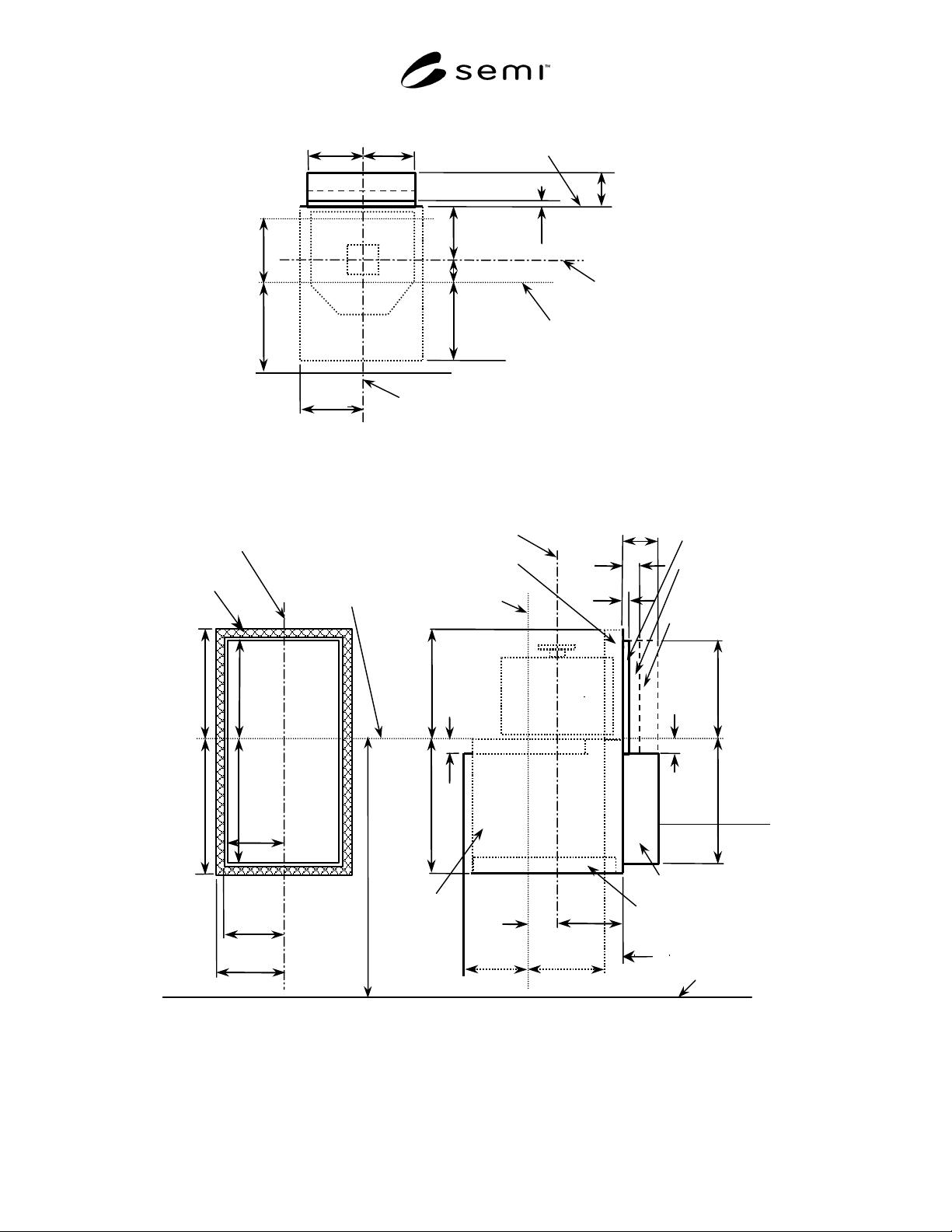
Figure 2
Top, Rear, and Side Views of BOLTS/Light Exclusion Volume and Equipment Side of the Side Interface
Feature