semi合集-English.pdf - 第7162页
SEMI S22-1103a © SEMI 2003, 2005 47 Table A1-11 Maximum Temperature L imit Parts of the Equipment Temperature Limit (°C) Knife switch blade and contact jaws 55 Fuse and fuse clip 110 Insulated conductors #1 Field wiring …
SEMI S22-1103a © SEMI 2003, 2005 46
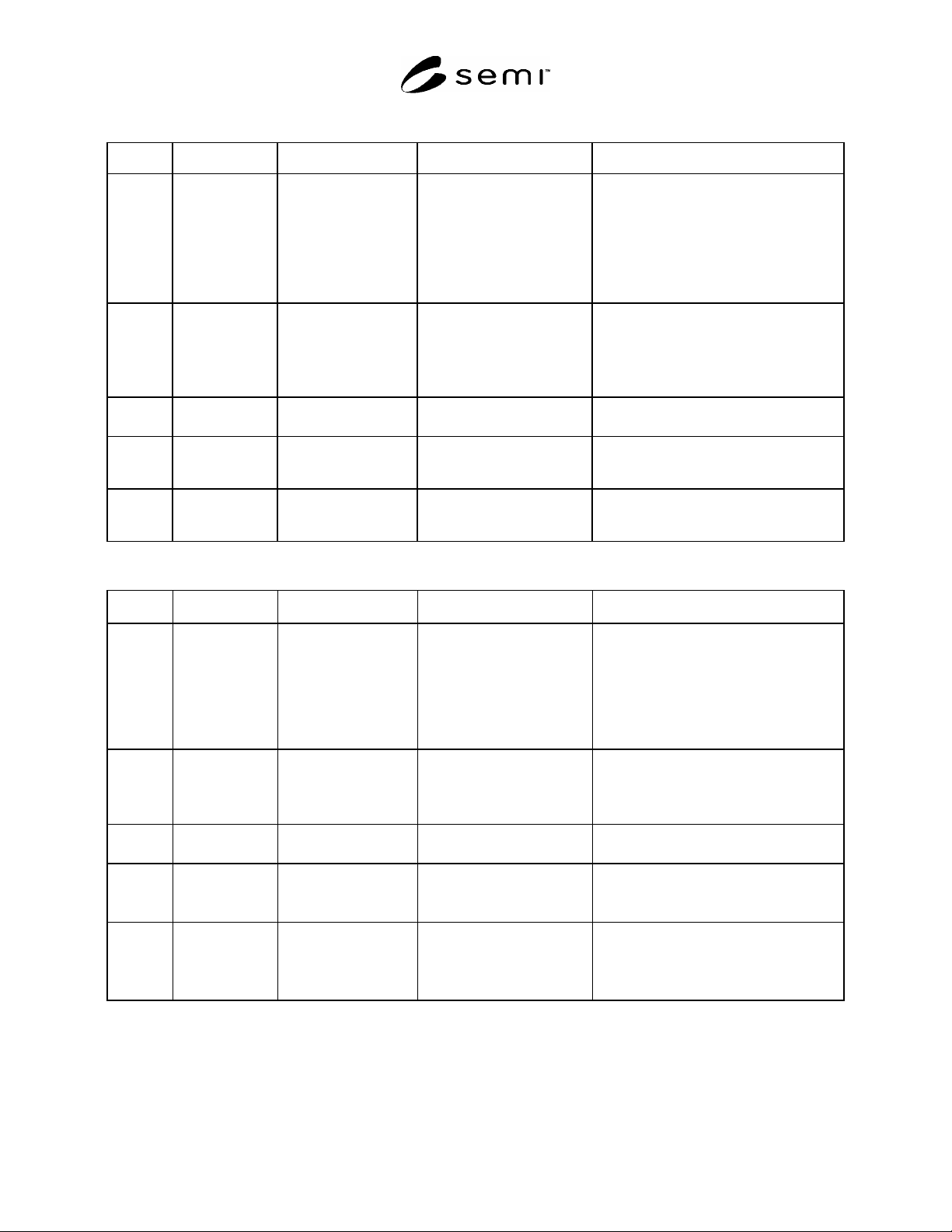
Table A1-9 Indicator Lights and Illuminated Pushbuttons With Respect To The Condition Of The Process
Color Meaning Explanation Action by Operator Examples of Application
Red Emergency Dangerous Condition Immediate Action To Deal
With A Dangerous Condition,
E.G. By
- Operating Emergency Off
(EMO)
- Opening Safety Valve
- Starting Cooling Pump
- Pressure/Temperature Of Main Fluid
Systems Out Of Safe Limits
- Voltage Drop
- Breakdown Of Main Unit
-Stopping Of Essential Machines, Service
Systems
-Deep-Freezer Temperature Too High
Yellow Abnormal - Abnormal Condition
- Impending Critical
Condition
Monitoring And/Or
Intervention (e.g., By
Reestablishing The Intended
Function)
- Pressure/Temperature Different From
Normal Level
- Tripping Of A Protecting Command
- Position Change Of A Valve
- Deep-Freezer On Super Freezing
Green Normal Normal Condition Optional - Authorization To Proceed
- Indication Of Normal Working Limits
Blue Mandatory - Indication Of
Condition That
Requires Action
Mandatory Action Indication To The Operator To Input
Information
White
Gray
No Meaning
Assigned
Not Safety Indicators Surveillance General Information (e.g., Confirmation O
f
A Command, Indication Of Measured
Values)
Table A1-10 Indicator Lights and Illuminated Pushbuttons With Respect To The State Of Equipment
Color Meaning Explanation
Action by Operator Examples of Application
Red Emergency Fault Condition Immediate Action To Deal
With A Dangerous Condition,
E.G. By
- Operating Emergency Off
(EMO)
- Opening Safety Valve
- Starting Cooling Pump
- Pressure/Temperature Of Auxiliary
Systems Out Of Safe Limits
- Stopping Of Necessary Service Systems
- Over-Traveling Of A Stop Position On A
Hoist
Yellow Abnormal Abnormal Condition
Monitoring And/Or
Intervention (e.g. By
Reestablishing The Intended
Function)
- Conveyor Overloaded
- Over-Traveling Of A Limit Switch
- Position Change Of A Valve Or Conveyor
Belt
Green Normal Normal Condition Optional - Authorization To Proceed
- Indication Of Normal Working Limits
Blue Mandatory Mandatory Significance Mandatory Action Indication Of A Need To Enter:
- Preset Values
- Other Mode Of Control
White
Gray
No Meaning
Assigned
--- --- Status Indication, E.G.
- Switch Open/Close
- Valve Open/Close
- Motor Stopped/Running
SEMI S22-1103a © SEMI 2003, 2005 47
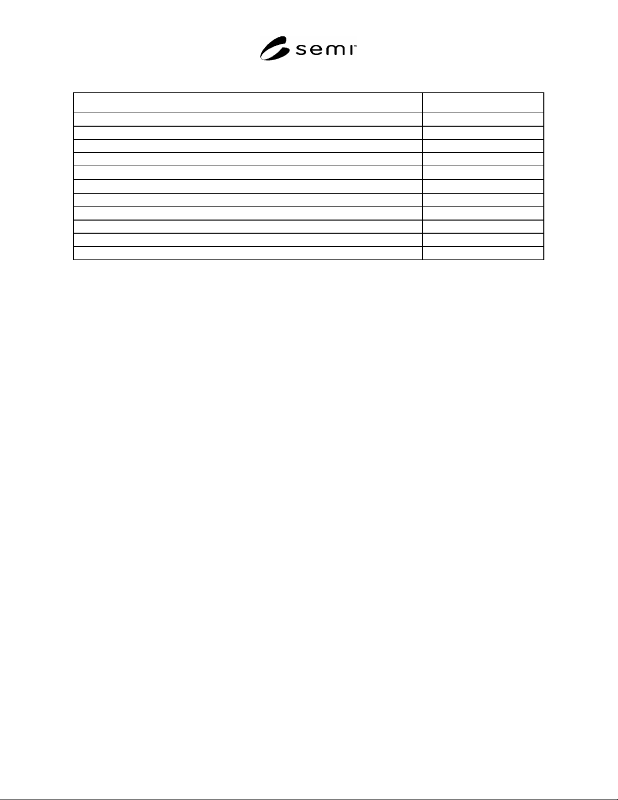
Table A1-11 Maximum Temperature Limit
Parts of the Equipment Temperature Limit (°C)
Knife switch blade and contact jaws 55
Fuse and fuse clip 110
Insulated conductors
#1
Field wiring terminals --
Equipment marked for 60 C or 60/75 C supply wires
75
Equipment marked for 75 C supply wires
90
Buses and connecting straps or bars 125
Capacitors
#2
Power switching semiconductors
#3
Printed wiring boards
#4
Motors and Transformers
#5
#1
The temperature as marked on the conductor or otherwise the rated temperature designated by the conductor manufacturer.
#2
The temperature marked on the capacitor or otherwise the rated temperature designated by the conductor manufacturer.
#3
The case temperature for the applied power dissipation recommended by the semiconductor manufacturer.
#4
The operating temperature of the board as specified by the board manufacturer.
#5
The rated temperature of the motor or transformer as specified by the manufacturer, if provided. When not provided, use appropriate standards
such as IEC 61010-1 for guidance.
SEMI S22-1103a © SEMI 2003, 2005 48
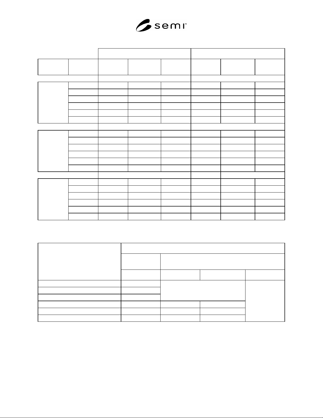
Table A1-12 Creepage and Clearance in Class 1000 or Less Cleanroom
Basic/Supplementary (mm) Double/Reinforced (mm)
Installation
Category
Working
Voltage
Clearance Creepage
Test Voltage,
Vrms
Clearance Creepage
Test Voltage,
Vrms
3
50 0.1 0.18 230 0.10 0.35 400
100 0.1 0.25 350 0.12 0.50 510
150 0.1 0.30 490 0.40 0.60 740
300 0.5 0.70 820 1.60 1.60 140-0
600 1.5 1.70 1350 3.30 3.40 2300
Category 1
1000 3.0 3.20 2200 6.50 6.50 3700
50 0.1 0.18 350 0.12 0.35 510
100 0.1 0.25 490 0.40 0.50 740
150 0.5 0.50 820 1.60 1.60 1400
300 1.5 1.50 1350 3.30 3.30 2300
600 3.0 3.00 2200 6.50 6.50 3700
Category 2
1000 5.5 5.50 3250 11.50 11.50 5550
50 0.1 0.18 490 0.4 0.4 740
100 0.5 0.50 820 1.6 1.6 1400
150 1.5 1.50 1350 3.3 3.3 2300
300 3.0 3.00 2200 6.5 6.5 3700
600 5.5 5.50 3250 11.5 11.5 5550
Category 3
1000 8.0 8.00 4350 16.0 16.0 7400
#1
Specified creepage distances less than 0.70 mm may be reduced on uncoated printed wiring boards according to the following table.
#2
Cleanroom Class 1000 or less is pollution degree 1, however the pollution degree in a particular area in a given piece of equipment may exceed
pollution degree 1, even if the equipment is installed in a cleanroom class 1000 or less.
PWB Creepage Distance
Basic or Supple-
mentary Insulation
Double or Reinforced
Equipment Creepage Distance, mm
Category 1 Category 2 Category 3
0.18 0.1
0.25 0.1
0.30 0.2
No reduction
0.35 0.10 0.12
0.50 0.5 0.20 0.40
0.60 0.45
No reduction
#3
If necessary to test using DC voltage, increase specified test voltage by 42 percent.