semi合集-English.pdf - 第5003页
SEMI M15-0298 © SE MI 1989, 1998 1 SEMI M15-0298 POLISHED WAFER DEFECT LIMITS TABLE FOR SEMI-INSUL A TING GALLIU M A RSENIDE WAFERS NOT E: This e ntire docum ent was r evised in 19 98. 1 Purpose 1.1 T his document define…

SEMI M14-89 © SEMI 19891
SEMI M14-89
SPECIFICATION FOR ION IMPLANTATION AND ACTIVATION
PROCESS FOR SEMI-INSULATING GALLIUM ARSENIDE SINGLE
CRYSTALS
1 Scope
The purpose of this document is to present a process for
ion implantation, activation, and measurement of the
resulting layers so that meaningful comparisons can be
made between various lots of semi-insulating GaAs.
This test will be performed by the supplier so that
product may be represented in a standard way.
NOTE: This is intended to be an interim procedure for
use until a standard test method is developed by ASTM.
2 Process
2.1 Candidate lots must pass SEMI GaAs
specifications for resistivity, mobility, and thermal
stability using standard ASTM referee techniques.
2.2 Implantation Process
2.2.1 Surface Preparation — The surface treatment
shall be designed to remove residual oxide.
2.2.2 Implant Angle Energy Species and Dose — An
energy of 150 keV using Si
29
to a dose of 2 × l0
12
/cm
2
and a tilt of 11° to 13° from the (100) toward the (110).
2.3 Activation Process
2.3.1 Surface Preparation — No chemical treatment
should be performed prior to activation.
2.3.2 Activation — The samples shall be subjected to a
temperature of 850°C for 10 minutes with a second
proximity wafer directly in contact with the implanted
surface. The proximity wafer shall be identical to the
subject wafer except not subjected to ion implantation.
The ambient of the furnace shall be a gas such as
nitrogen or argon.
2.4 Layer Evaluation
2.4.1 Evaluation of the activated samples shall be
based upon CV profiling, mobility, and resistivity as
specified according to standard ASTM techniques.
NOTICE: These standards do not purport to address
safety issues, if any, associated with their use. It is the
responsibility of the user of these standards to establish
appropriate safety and health practices and determine
the applicability of regulatory limitations prior to use.
SEMI makes no warranties or representations as to the
suitability of the standards set forth herein for any
particular application. The determination of the
suitability of the standard is solely the responsibility of
the user. Users are cautioned to refer to manufacturer’s
instructions, product labels, product data sheets, and
other relevant literature respecting any materials
mentioned herein. These standards are subject to
change without notice.
The user’s attention is called to the possibility that
compliance with this standard may require use of
copyrighted material or of an invention covered by
patent rights. By publication of this standard, SEMI
takes no position respecting the validity of any patent
rights or copyrights asserted in connection with any
item mentioned in this standard. Users of this standard
are expressly advised that determination of any such
patent rights or copyrights, and the risk of infringement
of such rights, are entirely their own responsibility.
Copyright by SEMI® (Semiconductor Equipment and Materials
International), 3081 Zanker Road, San Jose, CA 95134. Reproduction o
f
the contents in whole or in part is forbidden without express written
consent of SEMI.
SEMI M15-0298 © SEMI 1989, 19981
SEMI M15-0298
POLISHED WAFER DEFECT LIMITS TABLE FOR SEMI-INSULATING
GALLIUM ARSENIDE WAFERS
NOTE: This entire document was revised in 1998.
1 Purpose
1.1 This document defines the ma ximum number of defects, by type, that an acceptable polished Semi-Insulating
Gallium Arsenide (GaAs) wafer may exhibit.
2 Scope
2.1 This document, established sep arately from SEMI M15, in accordance with the latest requirements for the
material in advanced applications, covers polished semi-insulating GaAs wafers. The defect limits table can also be
applied to conducting GaAs wafers, except for the specification of Light Point Defects (LPD) mentioned hereinafter.
“Polished” shall refer to those wafers which have a specular chemical or chemical/mechanical finish applied to one
side of the wafer, with the backside being as cut and etched, lapped and etched, ground and etched, or polished. The
definition of defects is covered in ASTM Practices F 523 and F 154.
3 Referenced Documents
3.1 ASTM Standards
1
F 154 — Practices and Nomenclature for Identification of Structures and Contaminants Seen on Specular Silicon
Surfaces
F 523 — Practice for Unaided Visual Inspection of Polished Silicon Slices
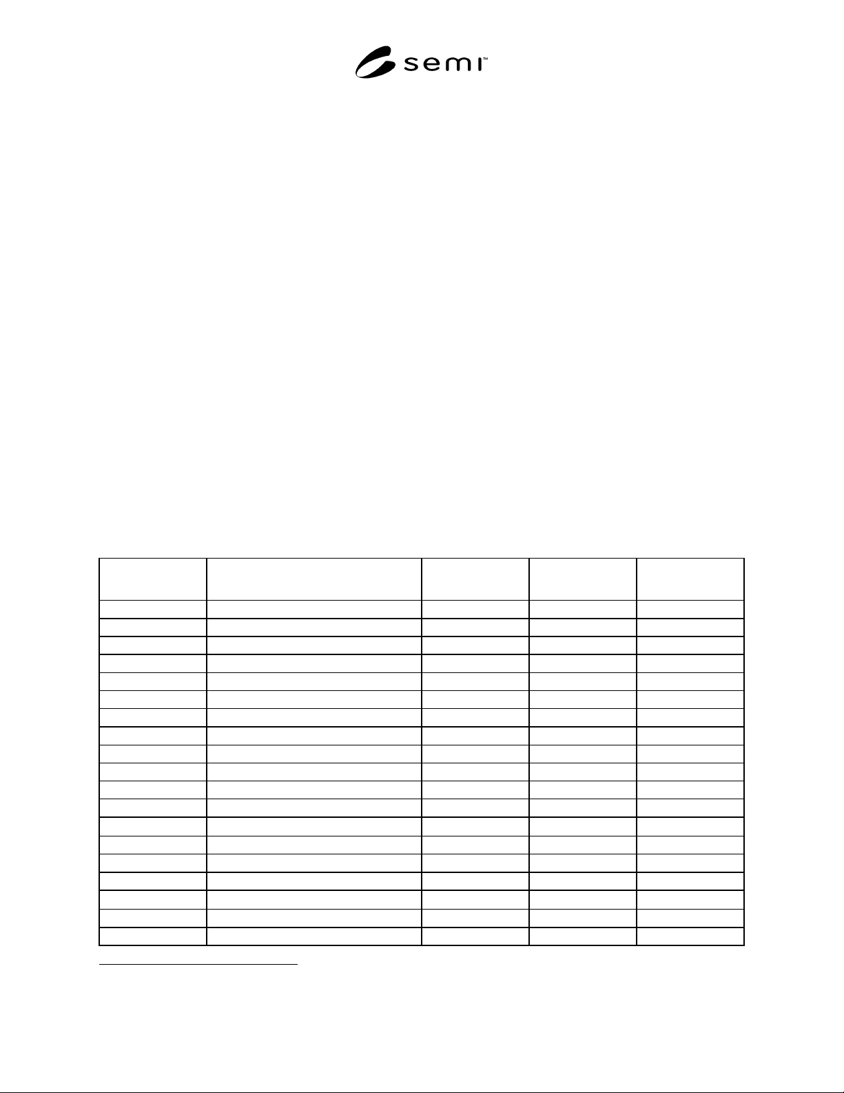
Table 1 Polished Wafer Defect Limits
Item # Characteristics — Front Surface
Maximum Defects
Limits Prime Wafer
Maximum Defects
Limits Test Wafer Notes
1 Scratches
Macroscratches None #1
Maximum Number ---- 3
Maximum Length ---- Radius/2
Microscratches None Not Specified #1, 2
2Pits #1, 2
2" Diameter Slices None 5
3" Diameter Slices None 15
4" Diameter Slices None 30
3 Haze None None #1, 2
4 Cavity/Voids None None #1
5 Contamination None None #1, 2
6
Light Point Defects ≥ φ 2.0 µm
2" Diameter Slices 10 20 #2, 3
3" Diameter Slices 15 30 #2, 3
4" Diameter Slices 20 40 #2, 3
Light Point Defects ≥ φ 3.0 µm
2" Diameter Slices 50 100 #2, 3
3" Diameter Slices 100 200 #2, 3
1 American Society for Testing and Materials, 100 Barr Harbor Drive, West Conshohoken, PA 19428-2959
SEMI M15-0298 © SEMI 1989, 1998 2
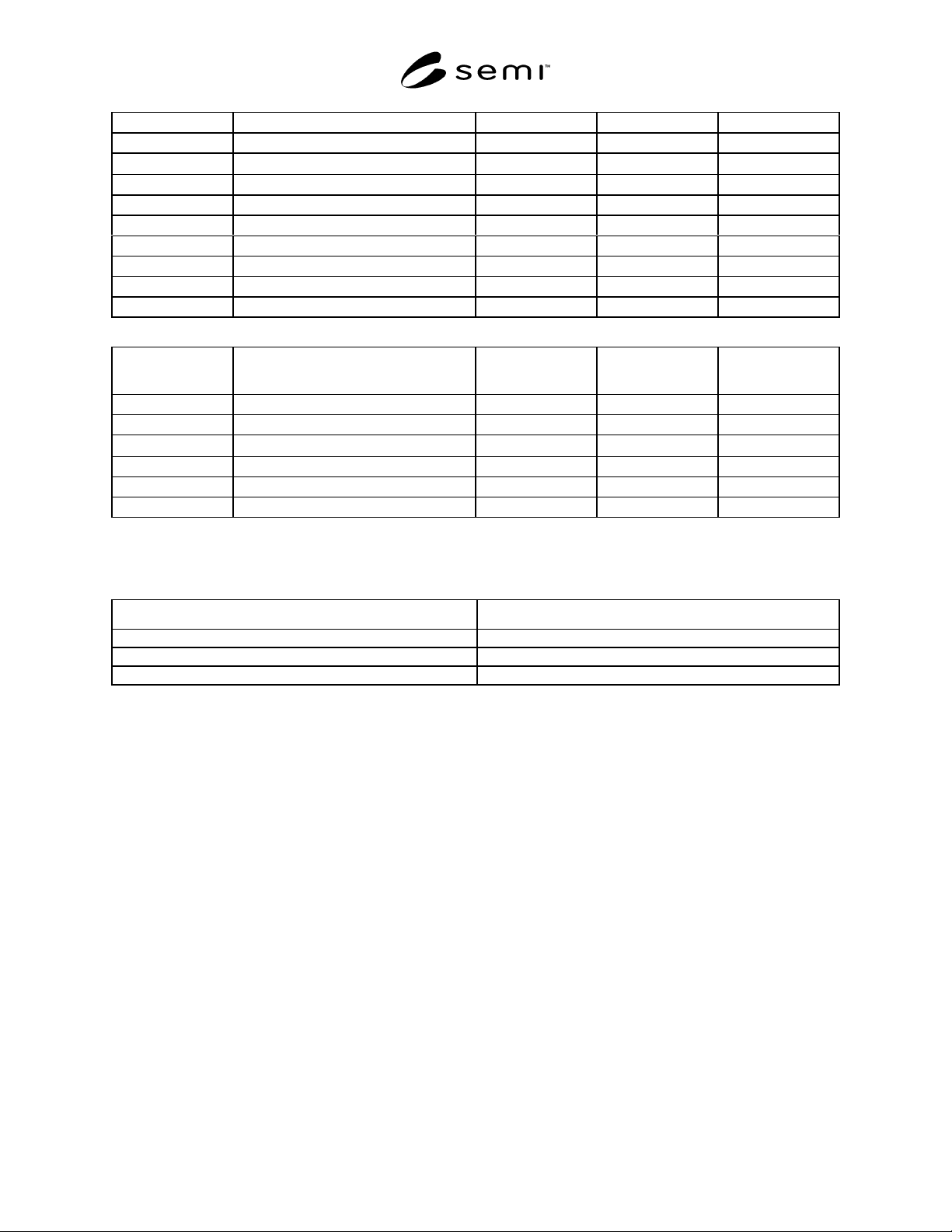
18
4" Diameter Slices 200 400 #2, 3
7
Chips (≥ 0.5 mm × 0.3 mm)
None None #1
8 Cracks None None #1
9 Dimples None None #1, 2
10 Gallium Inclusions/Precipitates None None #1, 2
11 Orange Peel None None #1, 2
12 Saw Marks None None #1
13 Striations None None #1, 2
14 Twins None None #1, 2
Item # Characteristics – Back Surface
Maximum Defect
LimitsPrime Wafer
Maximum Defect
LimitsTest Wafer Notes
15 Stain None None #2, 4
16 Saw Marks None None #1, 5
17
Chips (≥ 0.5 mm × 0.3 mm)
None None #1
18 Cracks None None #1
19 Listed Defects #10, 14 None None #1, 2
20 Listed Defects #1, 2, 6 #6
NOTES:
1. These defect limits are meant to apply only to those characteristics which can be seen with the unaided eye under high-intensity illumination
according to ASTM Practice F 523. Limits for other defects listed and defined in this section which require the aid of a microscope, preferential
etching, or other apparatus must be agreed upon between supplier and user.
2. Peripheral Edge Allowance — The outer edge exclusion for observation shall be determined from the following tabe:
Diameter Outer Edge Exclusion for Observation
2 inch 2 mm
3 inch 3 mm
4 inch 3 mm
3. LPD shall be counted by measuring equipment designed for detecting laser light scatter. Selection of the measuring equipment and the
requirement for the precision are to be agreed upon between supplier and user.
4. Back Surface Stain — An area of undercutting, texturing, or oxidation, common in waxless polished wafers.
5. The depth of allowed saw marks is to be no greater than 5 µm. The measuring method is to be agreed upon between supplier and user.
6. Item #20 — To be agreed upon between supplier and user.
NOTICE: These standards do not purport to address safety issues, if any, associated with their use. It is the
responsibility of the user of these standards to establish appropriate safety and health practices and determine the
applicability of regulatory limitations prior to use. SEMI makes no warranties or representations as to the suitability
of the standards set forth herein for any particular application. The determination of the suitability of the standard is
solely the responsibility of the user. Users are cautioned to refer to manufacturer’s instructions, product labels,
product data sheets, and other relevant literature respecting any materials mentioned herein. These standards are
subject to change without notice.
The user’s attention is called to the possibility that compliance with this standard may require use of copyrighted
material or of an invention covered by patent rights. By publication of this standard, SEMI takes no position
respecting the validity of any patent rights or copyrights asserted in connection with any item mentioned in this
standard. Users of this standard are expressly advised that determination of any such patent rights or copyrights, and
the risk of infringement of such rights, are entirely their own responsibility.
Copyright by SEMI® (Semiconductor Equipment and Materials
International), 3081 Zanker Road, San Jose, CA 95134. Reproduction o
f
the contents in whole or in part is forbidden without express written
consent of SEMI.