semi合集-English.pdf - 第3644页
SEMI E142-0705 © SEMI 2005 6 Table 4 XYDimensions Type Attribute Name Definition Access Reqd Form X The physical offset from the origin along the X axis, according to the values of SubstrateMap coordinate attributes; Sub…
SEMI E142-0705 © SEMI 2005 5
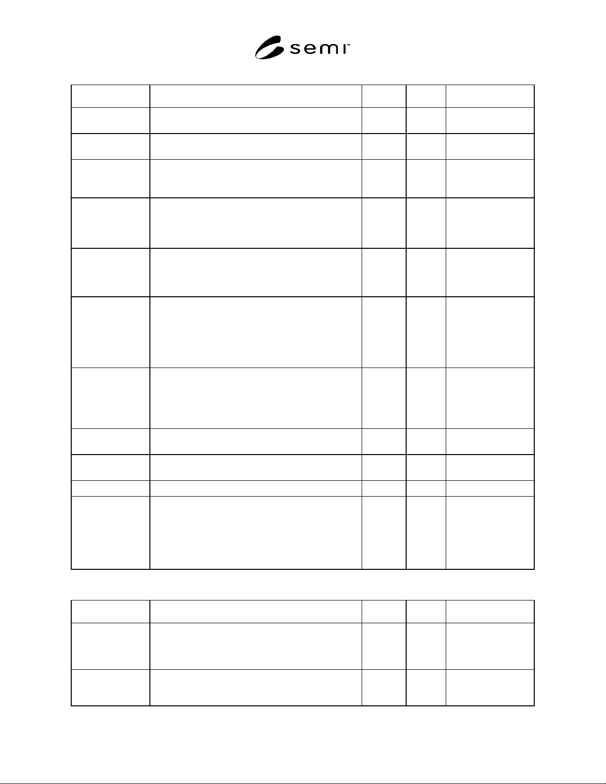
Table 2 Layout Attributes
Attribute Name Definition Access Reqd Form
LayoutId The layout identifier. This must be unique within the
scope of MapData.
RO Y Text
DefaultUnits The units in which physical dimensions and coordinates
are represented unless otherwise specified.
RO Y Text
Dimension The number of columns (X-axis) and rows (Y-axis) in the
layout.
If this is the top level layout then X = 1, Y = 1.
RO Y LogicalCoordinates
(see Table 3)
DeviceSize The X and Y dimensions of the device.
If this is the top level layout, then this defines the size of
the substrate itself.
If not present, then DeviceSize is not defined.
RO N XYDimensions
(see Table 4)
StepSize The distance from a reference point on one device to the
same reference point on the adjacent device. StepSize –
DeviceSize is equal to the “street” width between devices.
If not present, then StepSize is not defined.
RO N XYDimensions
(see Table 4)
LowerLeft The distance in microns of the lower left corner of this
layout from the lower left corner of the parent layout.
If this is the top level layout, then LowerLeft.X = 0 and
LowerLeft.X = 0.
If not present, then LowerLeft.X = 0 and LowerLeft.X =
0.
RO N XYDimensions
(see Table 4)
Z The logical and physical height of the device above (or
below) the parent layout.
If this is the top level layout, then Z.Order = 0 and
Z.Height = 0.
If not present, then Z.Order = 0 and Z.Height = 0.
RO N ZDimensions
(see Table 5)
TopImage Name of an image file showing the top side of an
individual device in the layout.
RO N Text
BottomImage Name of an image file showing the bottom side of an
individual device in the layout.
RO N Text
ProductId Product identifier for a device in this layout. RO N Text
TopLevel TopLevel = True implies that this is a top level layout.
TopLevel = False implies that this layout is the child of
another layout.
If this is the top level layout, then TopLevel = True.
If not present, then TopLevel = False. TopLevel may be
omitted from child layouts.
RO N Boolean
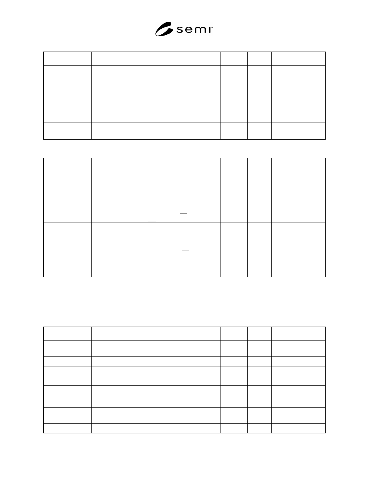
Table 3 LogicalCoordinates Type
Attribute Name Definition Access Reqd Form
X The column or X logical coordinate, according to the
values of SubstrateMap coordinate attributes;
SubstrateSide, Orientation, OriginLocation, and
AxisDirection.
RO Y Integer
Y The row or Y logical coordinate, according to the values
of SubstrateMap coordinate attributes; SubstrateSide,
Orientation, OriginLocation, and AxisDirection.
RO Y Integer
SEMI E142-0705 © SEMI 2005 6
Table 4 XYDimensions Type
Attribute Name Definition Access Reqd Form
X The physical offset from the origin along the X axis,
according to the values of SubstrateMap coordinate
attributes; SubstrateSide, Orientation, OriginLocation, and
AxisDirection.
RO Y Floating point value
Y The physical offset from the origin along the Y axis,
according to the values of SubstrateMap coordinate
attributes; SubstrateSide, Orientation, OriginLocation, and
AxisDirection.
RO Y Floating point value
Units The units in which X and Y coordinates are represented.
If omitted then the Layout, DefaultUnits is used.
RO N Text
Table 5 ZDimensions Type
Attribute Name Definition Access Reqd Form
Order The order of the layouts in the Z dimension, according to
the values of SubstrateMap coordinate attributes;
SubstrateSide, and Orientation.
Layouts with higher values for Order are in front of those
with smaller values.
If this is the top level layout, then Order =0
.
If not present, then Order =0.
RO N Integer
Height The height of the device above (or below) the parent
layout, according to the values of SubstrateMap
coordinate attributes; SubstrateSide, and Orientation.
If this is the top level layout, then Height =0
.
If not present, then Height =0.
RO N Floating point value
Units The units in which Height is represented.
If omitted then the Layout.DefaultUnits is used.
RO N Text
11 Substrate
11.1 The Substrate object identifies a substrate to which a SubstrateMap may be assigned. A Substrate object may
have one or more AliasId objects.
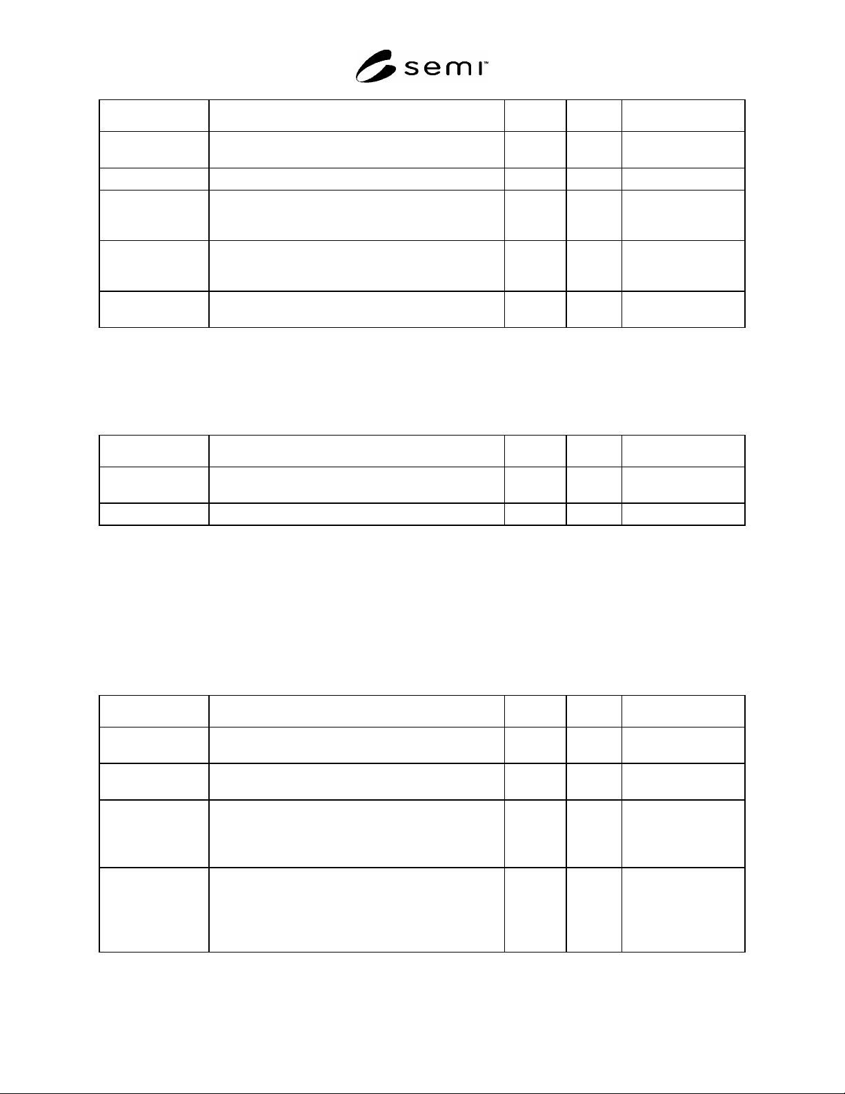
Table 6 Substrate Attributes
Attribute Name Definition Access Reqd Form
SubstrateType The type of substrate. A choice of ‘Wafer’, ‘Frame’,
‘Strip” or ‘Tray”.
RO Y Text
SubstrateId The substrate identifier. RO Y Text 1 to 32 characters
LotId Production lot identifier for this data. RO N Text 1 to 32 characters
CarrierType The type of wafer carrier, e.g. ‘Cassette’, ‘FOUP’, etc. RO N Text
CarrierId A character code that may be printed or encoded on the
substrate carrier, which uniquely identifies the substrate
carrier.
RO N Text 1 to 32 characters
SlotNumber This identifies the slot in the carrier in which the substrate
is placed.
RO N Positive Integer
SubstrateNumber Identifies the substrate within a lot. RO N Positive Integer
SEMI E142-0705 © SEMI 2005 7
Attribute Name Definition Access Reqd Form
GoodDevices The total number of “good” devices on the substrate. The
definition of “good” is beyond the scope of this document.
RO N Positive Integer
SupplierName Name of the supplier of the substrate. RO N Text
CreateDate Date and time when the map data is acquired: formatted a
s
YYYYMMDDhhmmsscc (year-month-date-hour-minute-
second-centisecond).
RO N Text
LastModified Date and time when the map data was last modified:
formatted as YYYYMMDDhhmmsscc (year-month-date-
hour-minute-second-centisecond).
RO N Text
Status Status of map data supplying process or preceding
process.
RO N Text
11.2 AliasId
11.2.1 The AliasId object contains other substrate identifiers that may be used to trace the substrate throughout the
substrate’s life cycle.
Table 7 AliasId Attributes
Attribute Name Definition Access Reqd Form
Type Type of identifier, e.g. “FrontsideId”, “BacksideId”,
“WaferId”, “FrameId” .
RO Y Text
Value Value of the identifier. RO Y Text 1 to 32 characters
12 SubstrateMap
12.1 The SubstrateMap object relates to a single substrate and layout and contains a list of one or more Overlay
objects. It may also include a substrate type specific object depending on the value of [SubstrateType].
12.2 If there are more than one SubstrateMap assigned to a Substrate and Layout combination they should differ in
either their Orientation, OriginLocation or both. For example there may be a map for the top side and one for the
bottom side of a Layout.
Table 8 SubstrateMap Attributes
Attribute Name Definition Access Reqd Form
SubstrateType A reference to the type of substrate to which the map data
applies.
RO Y Text
SubstrateId A reference to the substrate identifier to which the map
data applies.
RO Y Text 1 to 32 characters
LayoutSpecifier A reference to the layout to which the map data applies.
The LayoutSpecifier defines the full path, using / as a
delimiter from the top level layout to the layout to be
specified for example; ”WaferLayout/L1/DeviceLayout”.
RO Y Text
SubstrateSide Coordinate system attribute that defines the side of the
substrate. Restricted to the values;
TopSide*
Bottom Side
* Default value if this item is not present.
RO N Text