semi合集-English.pdf - 第3583页
SEMI E139-0705 © SEMI 2005 7 Error — The Error type is a structure that contains information about an error that has occurre d. The form of the structure is implem entation dependent and shal l be defi ned by each s ub…

SEMI E139-0705 © SEMI 2005 6
6 Conventions
6.1 The following conventions are used in this document:
To highlight terms specific to RaP, a term appears in italics within the specification. Italicized terms include
class names, attributes, and services. Service names also end in (), for example “getPDE()”.
To prevent the definition of numerous message parameters named "XxxList," this document adopts the
convention of referring to the list as "list of Xxx". In this case, the definition and data type of the parameter will
be given (not the type of the list). The term "list" indicates a collection (or set) of zero or more items of the
same data type.
6.2 Object Modeling
6.2.1 Unified Modeling Language (UML)
6.2.1.1 This specification uses UML notation for all class diagrams and for any object diagrams provided as
examples. No other types of object modeling diagrams are used in this specification.
6.2.2 Class Diagrams
6.2.2.1 UML class diagrams have clearly defined meaning and are a part of this specification. Detail contained in
these diagrams is not necessarily repeated in the text.
6.2.3 Name of a Class
6.2.3.1 The text capitalizes class names. Class attributes and services begin with lowercase letters.
6.2.4 Abstract and Concrete Classes
6.2.4.1 Each class is specified as Abstract or Concrete. Abstract classes are not directly implemented (that is, there
are no instances). All classes defined as concrete may be directly implemented. In UML class diagrams, abstract
class names are shown in italics.
6.2.5 Class Attribute Definition
6.2.5.1 The attributes of a class are defined in table format as illustrated by Table 1 below. Note that the “+” sign in
front of attributes in UML class diagrams indicates “public” attributes. All attributes defined in this specification
are public, therefore the “+” sign is omitted.
Table 1 Attribute Table Format
Attribute Name Definition Access Reqd Form
RO or
RW
Y or
N
See list below.
6.2.5.1.1 Access — Attributes may be settable (ReadWrite or RW) or not settable (ReadOnly or RO) through an
interface to the service provider.
4
6.2.5.1.2 Reqd — Is this attribute required? Y – Yes, or N – No.
6.2.5.1.3 Form — Defines the data type of the attribute. Data types in this specification are high-level definitions
and should be mapped to the data types of a specific technology as appropriate. In this specification, these data
types are also used for the parameters of message services.
Binary — A sequence of bytes that may have any value. Binary values are sometimes called “unformatted”
because their structure is not apparent.
Boolean — Takes the value of “true” or “false”.
Enumeration — A format that allows a specified list of possible values. In this document, these values are
represented as text strings, but may be implemented differently (e.g. as integers that correspond to the named
values).
4 The attribute table is a common format used by multiple standards. Note that all attributes defined by RaP are ReadOnly (RO).

SEMI E139-0705 © SEMI 2005 7
Error — The Error type is a structure that contains information about an error that has occurred. The form of
the structure is implementation dependent and shall be defined by each sub-specification of RaP that describes
messaging using a specific technology (for example SECS-II or XML/SOAP).
Integer — A numeric value. Integers are always whole numbers. The form and number of bytes is left to the
implementation definition.
Real — A numeric value that may represent any whole or fractional number. The form and number of bytes is
left to the implementation definition.
String — A text string. Limitations on length are left to the implementation technology unless otherwise
specified in this document. Strings are recommended to be implemented as UTF-8.
Checksum — A checksum value calculated on a specific stream of data using a specific method of calculation.
Time — Representation of the date and time of the occurrence of interest. The structure and form of items of
this type is left to the implementation.
UUID — Universally unique identifier created according to the ISO specification referenced in ¶4.2 and
represented as ASCII characters. Note that this type is represented by all-caps “UUID” to differentiate it from
the “uuid” ISO standard string definition that defines the content of an attribute of type “UUID”.
Any — The format may be any of the others listed in this section. Format is determined by the implementation.
list of xxx — An item that can hold multiple instances of a specified type (where xxx is the data type).
6.2.6 Association Documentation
6.2.6.1 Associations are documented using the form of Table 2. Only Navigable Associations for the class of
interest are included in the table. See ¶6.2.7 for explanation of Navigable Associations.
6.2.6.2 For each association, the table lists the Type, Description, Associated Class, Role, and Cardinality
Type — The type of association. The possible values include Composition, Aggregation, and Association. See
the UML standard in ¶4.3 for an explanation of these types of association.
Description — Text describing the association.
Associated Class — The name of the class connected by this association.
Role — The role name of the associated class in the association taken from the UML diagram. Composition
associations are not given roles in this document, since it usually implies containment of the aggregated objects.
Cardinality — How many of the associated class may be associated with this class – documented in UML form.
Table 2 Navigable Associations for Class xxx
Type Description Associated Class Role Cardinality
6.2.7 Association Navigability
6.2.7.1 UML associations include the concept of “Navigability”. When an association is navigable, the association
may be traversed to reach the class instance at the opposite end of the association (target object).
6.2.7.2 By default, an association is navigable in both directions. If an arrowhead is shown on one end of an
association, then navigability exists only in that direction.
6.2.7.3 From any object, it must be possible to obtain a reference to the target objects of any of its navigable
associations. For any navigable association defined in this document, this is required of the implementer. The
method of referencing the target objects is implementation dependent and is not specified in this document.
SEMI E139-0705 © SEMI 2005 8
7 Overview of RaP
7.1 The RaP specification is focused on the definition, management, and transfer of equipment recipes. In RaP, the
recipe components are called ProcessDefinitionElements
or PDEs. This section describes the high level view of the
concepts and the requirements that contribute to meet the purpose of this specification as described in §1.
7.2 This RaP overview makes reference to requirements defined later in the document. However, no statement in
this overview section defines a requirement. This overview is intended to provide a general understanding of the
RaP concepts so that the detailed requirements that follow can be more easily understood.
7.3 RaP Participants
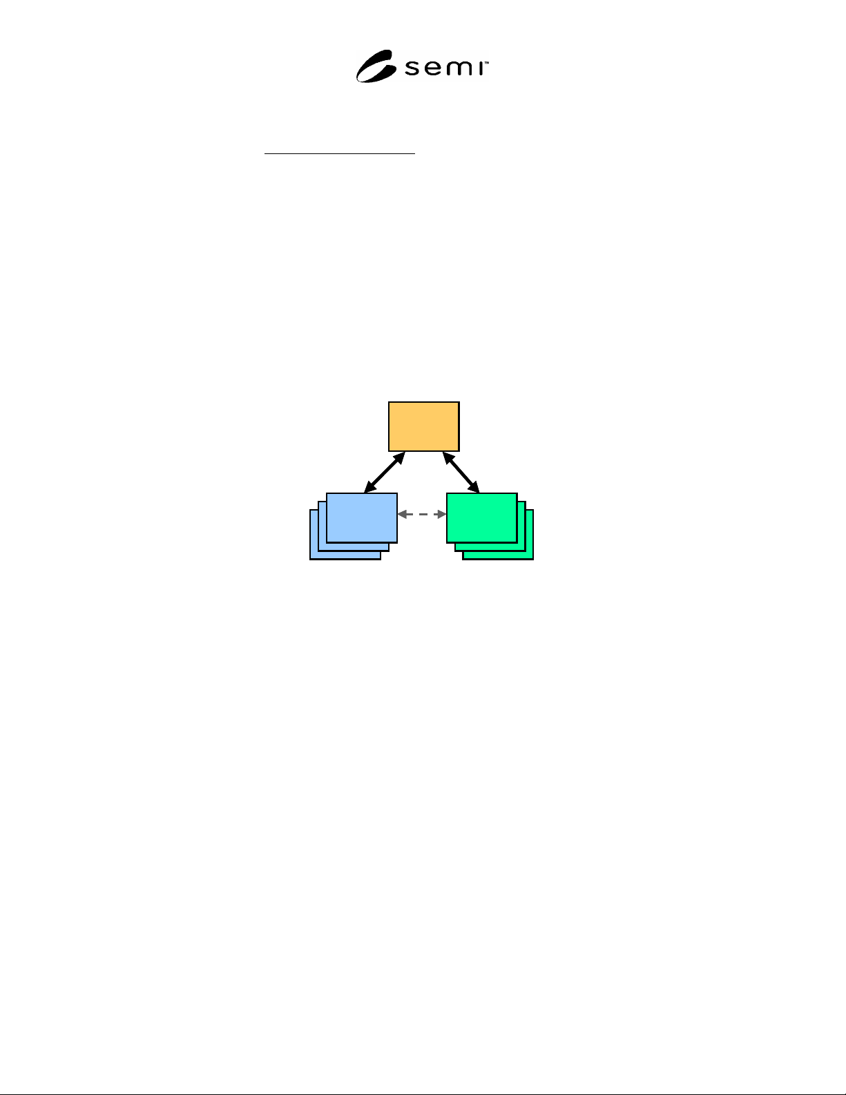
7.4 RaP assumes that there are three participants in the management of recipes – the FICS, the Equipment, and the
PDEeditor. When these provide RaP services, they become “RaPnodes” – the FICS becomes an FICSnode, the
Equipment becomes an EquipmentNode, and the PDEeditor becomes an EditorNode.
7.5 These three participants must work together to achieve the goals of recipe management. They may exist as
independent entities using defined message services (RaPnodes) or may be combined in some cases (as the editor is
often integrated into the equipment). Since integrated modules need no standardized communications, RaP defines
the services and data needed for these participants to exist independently as shown in Figure 2.
Equipment
Node
Equipment
Node
Editor
Node
Editor
Node
Equipment
Node
Editor
Node
FICS
Node
Equipment
Node
Equipment
Node
Editor
Node
Editor
Node
Equipment
Node
Editor
Node
FICS
Node
Figure 2
RaPnodes
7.6 RaP Environment
7.6.1 In discussing recipe management, one can divide the topic into three logically separate activities:
Execution of recipes
Creation and editing of recipes
Tracking and storage of recipes
7.6.2 RaP does not specify exactly how to perform any of these three activities. However, these activities define the
context in which RaP defined services and concepts are to be applied. The recipes themselves must reflect certain
aspects of these activities.
7.7 Execution of Recipes
7.7.1 When an activity is performed on an equipment, that activity must be fully specified in order for execution to
occur. RaP describes the main specification (recipe) and also parameters that can be set to amend the recipe. It does
not define the process for execution of the recipe.
7.7.2 RaP assumes that the equipment or some component of the equipment represents the target for the execution
of a recipe. In this document, that target is referred to as a Process Module. RaP assumes that there is a way to
identify a Process Module and that certain characteristics of that Process Module are known to the factory (make,
model, supplier, etc.).
7.7.3 RaP is compatible with SEMI E120. In terms of SEMI E120, the Process Module corresponds to the
“AbstractModule” class. The AbstractModule class models parts of the equipment structure capable of processing
material. Its attributes include “recipeType” which specifies the type of recipes that the AbstractModule can