semi合集-English.pdf - 第144页
SEMI E19.3-0697 © SEMI 1991, 2002 2 product data sheets, and other relevant literatu re respecting any materials mentioned herein. These standards are subject to change without noti ce. The user’s attention is called to …
SEMI E19.3-0697 © SEMI 1991, 2002 1
SEMI E19.3-0697 (Reapproved 0702)
PORT STANDARD FOR MECHANICAL INTERFACE OF WAFER
CASSETTE TRANSFER, 150 mm (6 inch) PORT
This standard was technically approved by the Global Physical Interfaces & Carriers Committee and is the
direct responsibility of the North American Physical Interfaces & Carrier Committee. Current edition
approved by the North American Regional Standards Committee on March 17, 2002. Initially available at
www.semi.org June 2002, to be published July 2002. Originally published in 1991; previously published June
1997.
The complete specification for this interface includes all general requirements of SEMI E19.
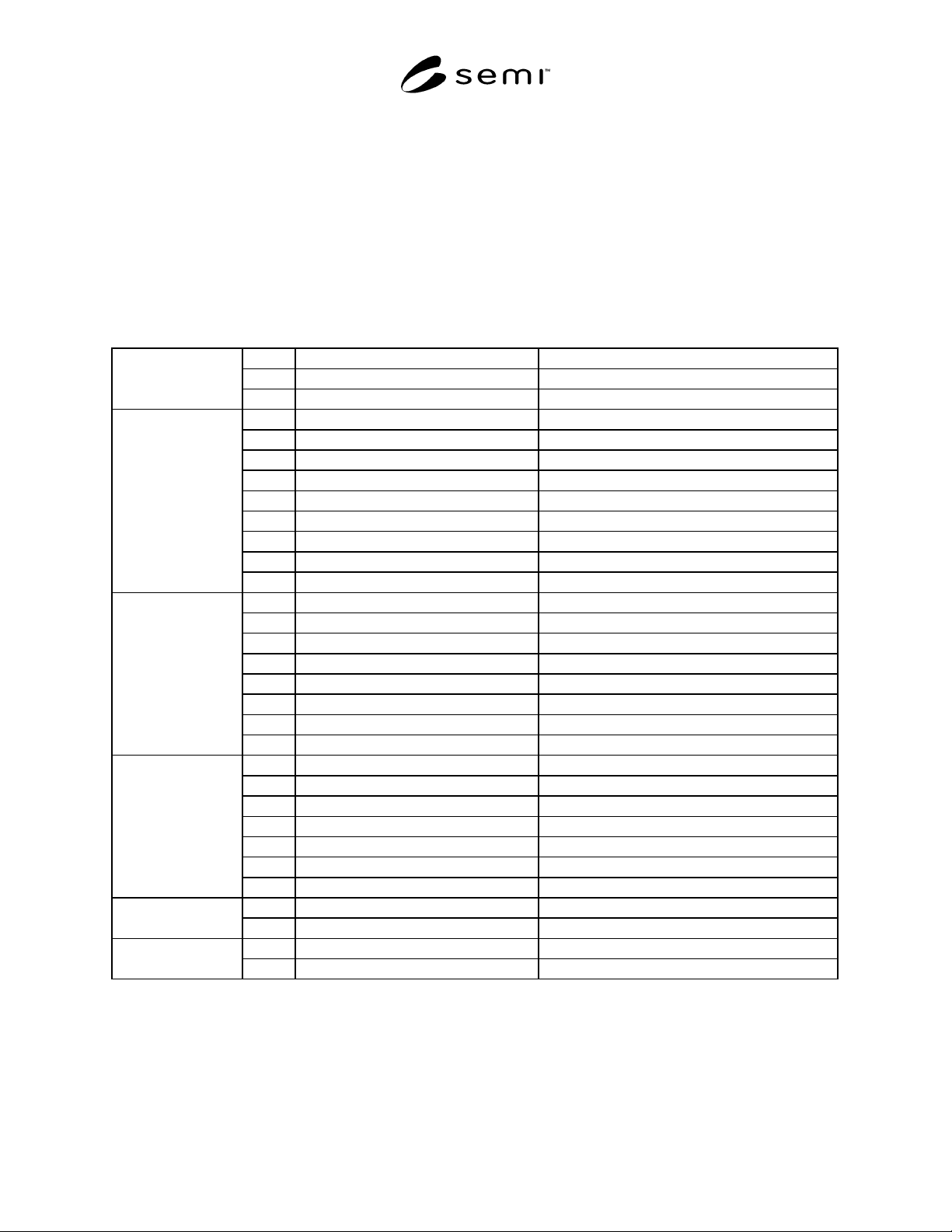
Table 1 Port Dimensions for 150 mm (6 in.) Wafer Cassette
A1 98.48 mm ± 0.13 mm (3.875 in. ± 0.005 in.)
A2 98.48 mm ± 0.13 mm (3.875 in. ± 0.005 in.)
Port Door
A3 9.53 mm ± 0.25 mm (0.375 in. ± 0.010 in.)
B1 115.57 mm ± 0.13 mm (4.550 in. ± 0.005 in.)
B2 107.95 mm ± 0.13 mm (4.250 in. ± 0.005 in.)
B3 6.35 mm ± 0.25 mm (0.250 in. ± 0.010 in.)
B4 6.35 mm ± 0.25 mm (0.250 in. ± 0.010 in.)
B5 17.78 mm (0.700 in.) maximum
B6
B7 12.70 mm (0.500 in.) minimum
B8 3.18 mm ± 0.25 mm (0.125 in. ± 0.010 in.)
Guide Rails
B9 6.35 mm (0.250 in.) maximum radius
C1 106.68 mm ± 0.13 mm (4.200 in. ± 0.005 in.)
C2 6.35 mm ± 0.13 mm (0.250 in. ± 0.005 in.)
C3 63.50 mm ± 0.13 mm (2.500 in. ± 0.005 in.)
C4 3.18 mm ± 0.05 mm (0.125 in. ± 0.002 in.) diameter
C5
C6 6.35 mm ± 0.25 mm (0.250 in. ± 0.010 in.)
C7 Full spherical radius
Latch Pins
C8 4.44 mm (0.175 in.) minimum
D1 152.40 mm ± 0.13 mm (6.000 in. ± 0.005 in.)
D2 76.20 mm ± 0.13 mm (3.000 in. ± 0.005 in.)
D3 165.10 mm ± 0.13 mm (6.500 in. ± 0.005 in.)
D4 82.55 mm ± 0.13 mm (3.250 in. ± 0.005 in.)
D5 6.35 mm ± 0.08 mm (0.250 in. ± 0.003 in.)
D6 10.16 mm ± 0.25 mm (0.400 in. ± 0.010 in.)
Registration
D7 Full spherical radius
F1 1.36 kg (3 lb) minimum Latch Pin Force each
F2 1.36 kg (3 lb) minimum
G1 12.70 mm ± 0.25 mm (0.500 in. ± 0.010 in.) Position of Cassette
G2 0.50 mm (0.020 in.) maximum
NOTICE: These standards do not purport to address safety issues, if any, associated with their use. It is the
responsibility of the user of these standards to establish appropriate safety and health practices and determine the
applicability of regulatory limitations prior to use. SEMI makes no warranties or representations as to the suitability
of the standards set forth herein for any particular application. The determination of the suitability of the standard is
solely the responsibility of the user. Users are cautioned to refer to manufacturer’s instructions, product labels,

SEMI E19.3-0697 © SEMI 1991, 2002 2
product data sheets, and other relevant literature respecting any materials mentioned herein. These standards are
subject to change without notice.
The user’s attention is called to the possibility that compliance with this standard may require use of copyrighted
material or of an invention covered by patent rights. By publication of this standard, SEMI takes no position
respecting the validity of any patent rights or copyrights asserted in connection with any item mentioned in this
standard. Users of this standard are expressly advised that determination of any such patent rights or copyrights, and
the risk of infringement of such rights, are entirely their own responsibility.
Copyright by SEMI® (Semiconductor Equipment and Materials
International), 3081 Zanker Road, San Jose, CA 95134. Reproduction o
f
the contents in whole or in part is forbidden without express written
consent of SEMI.

SEMI E19.4-0998
E
© SEMI 1992, 2003 1
SEMI E19.4-0998
E
(Reapproved 0703)
200 mm STANDARD MECHANICAL INTERFACE (SMIF)
This standard was technically reapproved by the Global Physical Interfaces & Carriers Committee and is the
direct responsibility of the North American Physical Interfaces & Carriers Committee. Current edition
approved by the North American Regional Standards Committee on March 12, 2003. Initially available at
www.semi.org May 2003; to be published July 2003. Originally published in 1992; previously published
March 2003.
NOTICE: The user’s attention is called to the
possibility that compliance with this standard may
require use of an invention covered by patent rights. By
publication of this standard, Semiconductor Equipment
and Materials International (SEMI) takes no position
with respect to the validity of any patent rights asserted
in connection with any item mentioned in this
document. Users of this document are expressly advised
that determination of any such patent rights, and the
risk of infringement of such rights, are entirely their
own responsibility.
1 Purpose
1.1 A standard interface is required for containers
intended to control the transport environment of
cassettes containing substrates. The interface must
address the proper container orientation for material
transfer and maintain continuity between the container
and equipment environment in order to control
particulate matter.
2 Scope
2.1 This specification describes one approach to
interfacing a clean cassette transport box to a clean
environmental housing on a piece of semiconductor
processing equipment or to other clean environments.
The system concept involves mating a door on a
cassette container to a door on an equipment enclosure
and transferring the cassette into, and out of, the
equipment without exposing the cassette and substrates
to outside contamination.
2.2 The incorporation of this standard may require
equipment designers to include the features of the
interface into the tool design. Spacing between open
cassette ports must be considered when incorporating
this interface. Designers are directed to the
specifications and recommendations made in SEMI E15
in this regard.
NOTICE: This standard does not purport to address
safety issues, if any, associated with its use. It is the
responsibility of the users of this standard to establish
appropriate safety and health practices and determine
the applicability of regulatory or other limitations prior
to use.
3 Limitations
3.1 This standard is specific to 200 mm wafers. This
specification focuses on applications in which the
interface port is positioned horizontally. The standard is
focused exclusively on the box-to-canopy interface.
Other considerations of box and equipment design are
purposely excluded.
NOTE 1: Hewlett Packard has patent coverage for this
concept and is offering non-exclusive licenses on an equal
basis to any company. Companies intending to manufacture
products to this standard should be aware of Hewlett
Packard' s position.
4 Referenced Standards
4.1 SEMI Standards
SEMI E15 — Specification for Tool Load Port
SEMI E19 — Standard Mechanical Interface (SMIF)
NOTICE: Unless otherwise indicated, all documents
cited shall be the latest published versions.
5 Terminology
5.1 (See Figure 1 for a pictorial depiction of most
terms.)
5.2 Definitions
5.2.1 box — a protective portable container for a
cassette and/or substrate(s).
5.2.2 cassette — an open structure that holds one or
more substrates (wafers, masks, etc.).
5.2.3 guide rail — a component of a port plate that
provides coarse location for placing the pod on the port
assembly.
5.2.4 hold-down latch — a mechanism for locking the
pod to the port plate.
5.2.5 latch pins — pins that engage the pod door latch
and accomplish the pod door lock/unlock functions.
Latch pins are carried by the port door.
5.2.6 pod — a box having a Standard Mechanical
Interface per SEMI E19.