semi合集-English.pdf - 第496页
SEMI E70-1103 © SEMI 1998, 2003 7 between production , industrial, and facilities engineering. The location is typically selected to optimize production flow within th e facility while minimizing accommodation costs and …
SEMI E70-1103 © SEMI 1998, 2003 6
5.2.45 site-specific facilities services and termination
matrix — a compilation of service types, quality, and
capacity available for use at utility point of connection
for a tool (see SEMI E51).
5.2.46 slurry system — a distribution system to convey
abrasive slurries for use in chemical mechanical
polishing (CMP) systems.
5.2.47 source inspection — inspection at the
equipment manufacturer’s factory to confirm
configuration details, review modifications, and
confirm installation designs prior to shipment of
equipment.
5.2.48 specialty gas — non-bulk process gases
typically stored in cylinders and used to supply one or
more process tools through specialized manifolds.
5.2.49 subfab — the area within the cleanroom
boundaries directly below the production level.
5.2.50 submittal — a written presentation for signed
acceptance of a proposal in response to a request for
services.
5.2.51 support equipment — ancillary equipment not
part of the main chassis.
5.2.52 time and materials (T&M) — a contracting
method whereby cost is determined by the actual
requirements of the project as opposed to an estimate
and a fixed cost system.
5.2.53 tool — any piece of semiconductor fabrication
or inspection equipment designed to process wafers.
Often used synonymously with equipment in the silicon
wafer processing industry.
5.2.54 tool accommodation — a methodology by
which semiconductor processing equipment is installed
in a cost-effective and timely manner.
5.2.55 turnkey — delivery of a fully functional and
tested system.
5.2.56 utility point of connection (UPOC)/tool point of
connection (TPOC) — UPOC is a fitting typically
located at a valve on a lateral to provide service for a
tool, the facilities end/termination of the hookup. TPOC
is a fitting typically at a valve on a processing tool
(either external or internal), the tool end/termination of
the hookup.
5.2.57 uninterruptable power supply (UPS) — a power
supply that provides an uninterrupted or continuous
supply of electrical power even during a failure in the
main utility power supply.
5.2.58 union labor — a group of trained craftpersons
that are represented by a single bargaining organization.
A labor bargaining unit.
5.2.59 value engineering — a set of reviews to
determine minimum requirements at a minimum cost.
5.2.60 valve manifold box (VMB)/valve manifold panel
(VMP) — a metal enclosure and/or panel including
distribution valves and components required to
distribute gases or liquids to multiple points of use from
a single source.
6 Roles and Responsibilities
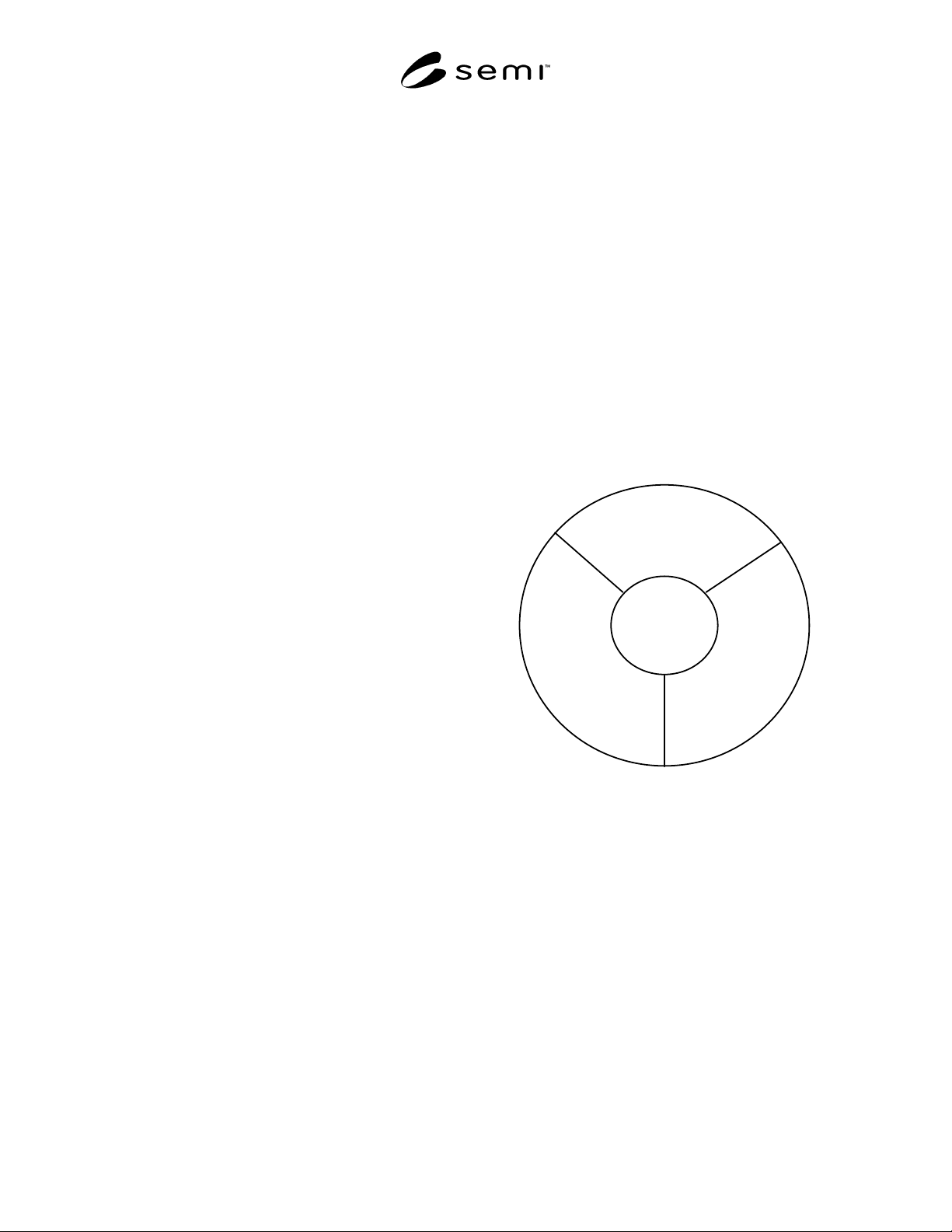
6.1 Definition and responsibility assignment are critical
to a successful project. Communications mechanisms
must be established as early as possible. SEMI E6
provides a template for establishing a format for
administrative interface. Using this format for
establishing interfaces will improve communication and
avoid cost and schedule impacts that might arise from
equipment or facilities modifications during the
procurement cycle. (See Figure 1.)
Tool
Supplier
Equipment
Engineer
Purchasing
Agent
Equipment
Installation
Manager
Figure 1
Information Exchange Relationships
7 Process
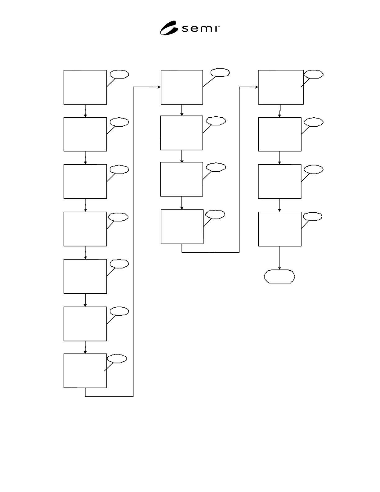
7.1 The following 15 steps describe a generic process
flow for using published tool accommodation standards
to achieve cost and schedule goals in a cycle of
procurement through acceptance for a particular process
tool. (See Figure 2.)
7.1.1 Process Requirement Defined by Customer —
Process parameters are defined and documented by the
process engineer and equipment engineer. Specific
performance targets are established that are consistent
with production requirements and cost of ownership
expectations.
7.1.2 Process Tool Location Identified by Customer —
Physical location is determined by collaboration
SEMI E70-1103 © SEMI 1998, 2003 7
between production, industrial, and facilities
engineering. The location is typically selected to
optimize production flow within the facility while
minimizing accommodation costs and production
interruptions. A layout document of record is generated
and approved by all affected parties.
7.1.3 Customer Generates Facilities Services Matrix
— Equipment and facilities engineering establish site-
specific parameters by using the SEMI E51 format to
define the available utilities and physical environment
within which the production tool will have to function.
Local jurisdictional and code requirement will be
comprehended by site specific parameters.
7.1.4 Customer Specifies Internal Tool Piping and
Distribution System Requirements — Site-specific
exceptions to SEMI E49 through SEMI E49.8 are
identified and reviewed with equipment suppliers to
determine the most cost- and schedule-efficient
configuration.
7.1.5 Customer Issues Formal Request for Quote — A
formal request for quotation (RFQ) is generated by the
customer’s procurement department soliciting
quotations from qualified manufacturers. SEMI E49
and SEMI E51 data are included with request for
quotation.
7.1.6 Supplier Submits Quote Including the Facilities
Interface Specification in SEMI E6 Format — A
“Statement of Conformance” to specified standards is
normally required for a quotation to be considered
valid. Exceptions to performance specifications must be
thoroughly documented and resolved. Multiple re-
quotation is sometimes required to establish a
contractually valid agreement.
7.1.7 Contractual Terms Finalized and Order is Placed
by Customer — Terms and conditions of the purchase
agreement based upon the finalized quotation are
negotiated and approved by all stakeholders.
7.1.8 Supplier Manufactures Equipment — Equipment
is manufactured per purchasing agreement. To prevent
errors and omissions during installation, change orders
are documented, approved prior to implementation, and
copies are distributed per administrative interfaces as
defined in SEMI E6.
7.1.9 Installation Detailed and Prefacilitation
Performed by Customer — Installation design
documentation is generated, approved, and distributed
to subcontractors for pricing. Long lead-time hookup
materials are identified and prepurchased.
Prefacilitation is performed to insure accurate and quick
hookup of tool on arrival.
7.1.10 Customer Source Inspects Equipment — Source
inspection is the final validation of all designs and
capabilities of the specific tool. Functionality testing is
performed and documented. Physical configuration is
confirmed. Modifications to configurations are
documented so that installation pricing can be adjusted
accordingly.
7.1.11 Supplier Ships Equipment to Customer —
Equipment is packaged per SEMI E49.1 and shipped as
defined in SEMI E6. Equipment is shipped per
purchase order stipulations. Customs clearance is
obtained as required.
7.1.12 Customer Verifies Equipment Matches Supplier
Provided Facilities Interface Specification — Upon
arrival at the customer site, verification of compliance
to purchase order is determined. Verification of
physical dimensions, point of connections, and interface
cabling and tubing is performed.
7.1.13 Equipment Hookup by Customer — Mechanical,
electrical, process piping, and life safety system
hookups are done, and all functional testing is
completed. Equipment is ready for vendor startup and
commissioning. Final payment to hookup contractor is
authorized, and upon payment, construction liens are
released. As-built drawings showing newly installed
tool are updated and submitted to owner for inclusion in
permanent records.
7.1.14 Equipment Is Qualified and Customer Verifies
Contract Completion — Equipment startup is complete
and functional testing to verify compliance to purchase
agreement is complete and documented. Final payment
to equipment vendor is released.
7.1.15 Actual Cost and Schedules Are Reviewed —
Final accounting is performed to determine actual costs
associated with the project. Actual duration of all
activities is compared to original schedule to determine
areas for improvement. Estimating models for future
installations are updated to reflect new information.
SEMI E70-1103 © SEMI 1998, 2003 8
P
r
o
c
e
s
s
R e q u i r e m e n t
D e f i n e d
b y
C
u
s
t
o
m
e
r
C
u
s
t
o
m
e
r
G
e
n
e
r
a
t
e
s
F
a
c
i
l
i
t
i
e
s
S
e
r
v
i
c
e
s
M
a
t
r
i
x
(
S
E
M
I
E
5
1
)
C
u
s
t
o
m
e
r
S
p
e
c
i
f
i
e
s
I
n
t
e
r
n
a
l
T
o
o
l
P
i
p
i
n
g
a
n
d
D
i
s
t
r
i
b
u
t
i
o
n
S
y
s
t
e
m
R
e
q
u
i
r
e
m
e
n
t
s
(
S
E
M
I
E
4
9
-
E
4
9
.
8
)
S u p p l i e r
S u b m i t s
Q
u
o
t
e
i
n
c
l
u
d
i
n
g
F
a
c
i
l
i
t
i
e
s
I
n
t
e
r
f
a
c
e
S
p
e
c
i
f
i
c
a
t
i
o
n
(
S
E
M
I
E
6
)
C
u
s
t
o
m
e
r
I
s
s
u
e
s
F
o
r
m
a
l
R
e
q
u
e
s
t
f
o
r
Q
u
o
t
e
w i t h
S E M I
E 5 1
&
E
4
9
D
a
t
a
C
o
n
t
r
a
c
t
u
a
l
T
e
r
m
s
F i n a l i z e d
&
O r d e r
P
l
a
c
e
d
b
y
C
u
s
t
o
m
e
r
T
o
o
l
L
o
c
a
t
i
o
n
I
d
e
n
t
i
f
i
e
d
b
y
C u s t o m e r
Installation
Detailed
and
Prefacilitation
Performed
by
Customer
Supplier
Ships
Equipment
to
Customer
(SEMI
E6
&
E49.1)
A
c
t
u
a
l
C
o
s
t
s
a
n
d
S
c
h
e
d
u
l
e
s
A
r
e
R
e
v
i
e
w
e
d
Cu
s
t
o
m
e
r
V
e
r
i
f
i
e
s
Equ
i
p
m
e
n
t
M
a
t
c
h
e
s
Su p p l i e r
P r o v i d e d
Fa c i l i t i e s
I n t e r f a c e
S
p
e
c
i
f
i
c
a
t
i
o
n
(
S
E
M
I
E
6
)
Equ
i
p
m
e
n
t
H
o
o
k
u
p
b
y
C
u
s
t
o
m
e
r
E
q
u
i
p
m
e
n
t
i
s
Q u a l i f i e d
a n d
Cu
s
t
o
m
e
r
V
e
r
i
f
i
e
s
C
o
n
t
r
a
c
t
C
o
m
p
l
e
t
i
o
n
E
n
d
P
r
o
c
u
r
e
m
e
n
t
M
a
n
u
f
a
c
t
u
r
i
n
g
I
n
s
t
a
l
l
a
t
i
o
n
7
.
1
.
1
7
.
1
.
2
7
.
1
.
3
7
.
1
.
4
7
.
1
.
5
7
.
1
.
6
7
.
1
.
7
7.1.9
7.1.11
7.1.12
7.1.13
7.1.14
7.1.15
Supplier
Manufactures
Equipment
7.1.8
Customer
Source
Inspects
Equipment
7.1.10
Figure 2
Tool Accommodation Process Flow Chart