semi合集-English.pdf - 第4470页
SEMI D17-0200 © SEMI 1998, 2000 5 Table 3 Cas sette Side Dom a ins Symbol Used Shown I n Datum Meas ured From Boundary or Fea ture Measur ed To Algebraic Relation or Value r1 Figure 3 center of coupling ex clusion zone o…
SEMI D17-0200 © SEMI 1998, 2000 4
symmetric about the bilateral and facial datum planes,
respectively. The top of this volume is half of z7 above
the nominal substrate seating plane and its bottom is z6
above the nominal substrate seating plane. The
substrate should be placed within the bounds of the
substrate set-down volume to avoid touching the edge
of the substrate to the side of the cassette.
6.12.4 The substrate pickup zone is defined by an area
indicated by dimensions x5 and y5 and is symmetric
about the bilateral and facial datum planes,
respectively. Its top and bottom are the upper and lower
tolerance of z6 around the nominal substrate seating
plane. If a substrate is placed in the substrate set-down
volume and is then pushed to the rear of the cassette,
then the entire bottom of the substrate must be
contained in the substrate pick-up zone.
6.13 Particle Generation — The cassette will not add
more than 0.05 particles/cm
2
of a size ≥ 0.5 µm (PSL
equivalent) per substrate pass per shipping cycle. The
shipping cycle is to be defined by the customer.
6.14 Inner and Outer Radii — All concave features
may have as much as a 1 mm (0.04 in.) radius to allow
for cleaning and to prevent contaminant build-up. All
required convex features (such as the robotic handling
flanges and the corners of the cassette top and bottom
domains) must also have a minimum radius of 1 mm
(0.04 in.) to prevent large stress contacts of the cassette
that might cause wear and particles.
6.15 Dimensional Tolerances — Width (W), Length
(L), and Height (H): ± 5 mm
6.16 Special Design Features
6.16.1 Compatible with automated cl eaning tools.
6.16.2 External features that are comp atible with
material handling systems such as, but not limited to,
Guided Vehicles, Stocker, and Conveyors.
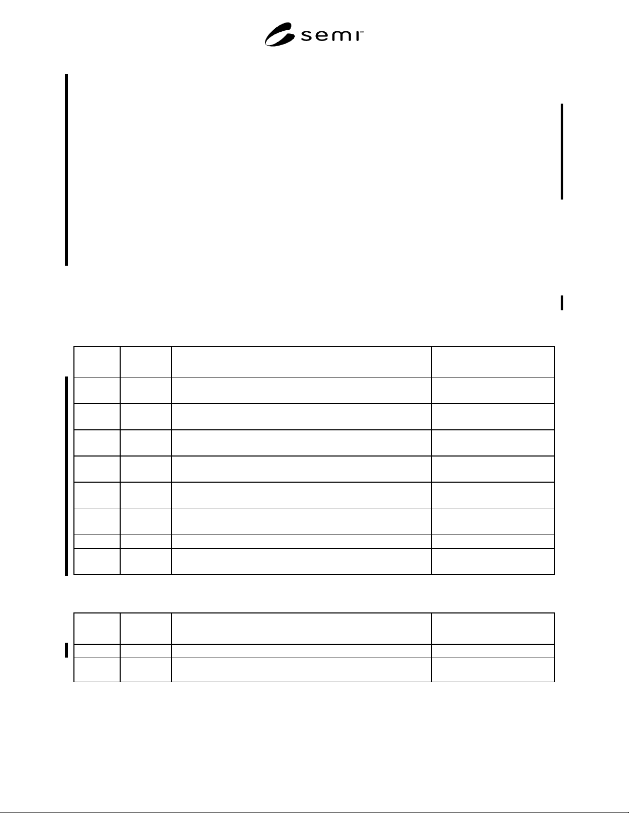
Table 1 Cassette Registration Type A Coupling Pin Dimensions
Symbol
Used
Shown In Dimensions Description Algebraic Relation or Value
d1 Figure 5 diameter of pin centered on the center axis line = 12 ± 0.05 mm
(0.4724 ± 0.002 in.)
r2 Figure 5 radial distance from the center axis line to the origin of shoulder
radius r5
= 6 mm
(0.2362 in.)
r3 Figure 5 radial distance from the intersection of the center axis line and z13 to
the top of the pin
= 15 ± 0.05 mm
(0.5906 ± 0.002 in.)
r4 Figure 5 blend radius for the intersection of r3 and r5 = 2 ± 0.1 mm
(0.0787 ± 0.004 in.)
r5 Figure 5 radial distance from the intersection of the horizontal datum plane
and r2 to the far shoulder of the pin
= 15 ± 0.05 mm
(0.5906 ± 0.002 in.)
r6 Figure 5 blend radius for the intersection of r5 and d1 = 2 ± 0.1 mm
(0.0787 ± 0.004 in.)
r7 Figure 5 roughness (R
a
) as defined in ISO 4287
0.30 µm (12 µin.) max.
z13 Figure 5 vertical distance from the horizontal datum plane to the origin of top
radius r3
= 2 ± 0 mm
(0.08 in.)
Table 2 Cassette Registration Type B Roller Pin Dimensions
Symbol
Used
Shown In Dimensions Description Algebraic Relation or Value
r8 Figure 7 radius about roller circumference revolved about the revolute axis = 4.8 ± 0.12 mm
r9 Figure 7 radius of roller measured from the tangential surface created by r8 to
the revolute axis
≥ 20 ± 0.12 mm
SEMI D17-0200 © SEMI 1998, 20005
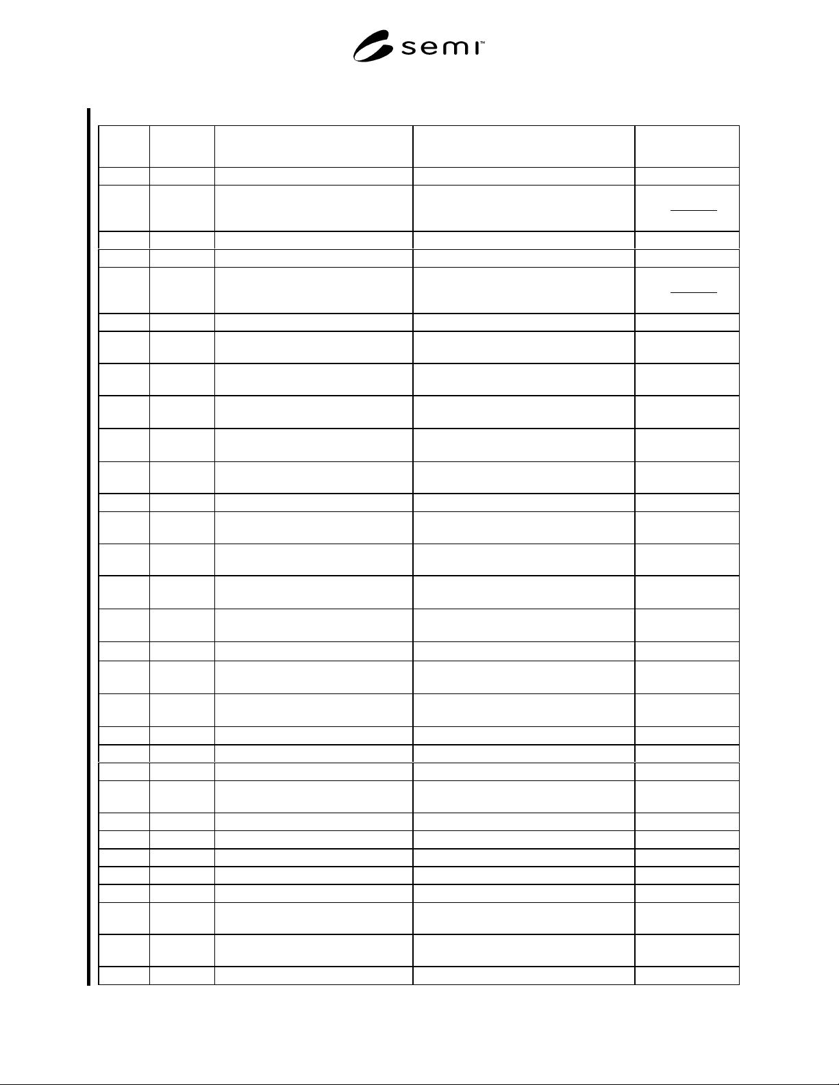
Table 3 Cassette Side Domains
Symbol
Used
Shown In Datum Measured From Boundary or Feature Measured To Algebraic
Relation or Value
r1 Figure 3 center of coupling exclusion zone outside edge of coupling exclusion zone < 15 mm
x1 Figure 2 bilateral datum plane encroachment of cassette side domains
on substrate extraction volume
2
57.0*W
≥
x2 Figure 2 bilateral datum plane outside edge of cassette side domains ≤ W + 37
x3 Figure 2 bilateral datum plane inside edge of rear cassette domains ≥ x1 – 40
x4 Figure 2 bilateral datum plane outside edge of rear cassette domains
2
57.0*W
≥
x5 Figure 2 nominal substrate center line outside edge of substrate pick-up zone ≥ W + 2
x6 Figures 2
and 4
nominal substrate center line encroachment of cassette side domains
on substrate extraction volume
≥ x5
x7 Figure 2 nominal substrate center line outside edge of cassette top and bottom
domain
≤ W + 37
x8 Figure 3 bilateral datum plane inside edge of cassette sensing pad areas
= W * 0.71 ±
5.0 mm
x9 Figure 3 bilateral datum plane outside edge of cassette sensing pad
areas
= W * 0.78 ±
5.0 mm
x10 Figure 4 bilateral datum plane encroachment of cassette top domain on
robotic handling flange space
≤ W * 1.02
x11 Figure 4 bilateral datum plane far side of robotic handling flanges ≤ W * 1.05
x12 Figure 3 bilateral datum plane inside edge of conveyor rail exclusion
zones
≥ W * 0.752
x13 Figure 3 bilateral datum plane outside edge of conveyor rail exclusion
zones
≤ W * 0.877
x14 Figure 3 bilateral datum plane center of coupling exclusion zones
= W * 0.9455 ±
0.1 mm
x15 Figures 3
and 6
bilateral datum plane centerline of v-rail roller
= W * 0.815 ±
0.2 mm
x16 Figure 6 bilateral datum plane centerline of float roller
= x19 ± 2.0 mm
x17 Figure 3 bilateral datum plane inside edge of facial datum plane v-
groove
= W * 0.0245 ±
0.2 mm
x18 Figure 3 bilateral datum plane outside edge of facial datum plane v-
groove
= W * 0.020 ±
0.2 mm
x19 Figure 6 bilateral datum plane left edge of v-groove exclusion zone ≥ W * 0.069
x20 Figure 6 bilateral datum plane right edge of v-groove exclusion zone ≥ W * 0.109
x21 Figure 6 bilateral datum plane inside edge of float roller exclusion zone ≤ W * 0.742
x22 Figure 6 bilateral datum plane outside edge of float roller exclusion
zone
≥ W * 0.884
y1 Figure 2 facial datum plane encroachment of cassette side domain ≥ L * 0.031
y2 Figure 2 facial datum plane encroachment of cassette side domain ≤ L * 0.454
y3 Figure 2 facial datum plane encroachment of cassette side domain ≥ L * 0.515
y4 Figure 2 facial datum plane encroachment of cassette side domain ≤ L * 0.938
y5 Figure 2 facial datum plane outside edge of substrate pick-up volume ≤ L + 1
y6 Figure 2 facial datum plane encroachment of cassette side domains
on substrate set-down volume
≥ L + 1
y7 Figure 2 facial datum plane encroachment of cassette side domains
on substrate extraction volume
≥ L + 3
y8 Figure 2 facial datum plane boundary of rear cassette domain ≤ L * 1.12
SEMI D17-0200 © SEMI 1998, 2000 6
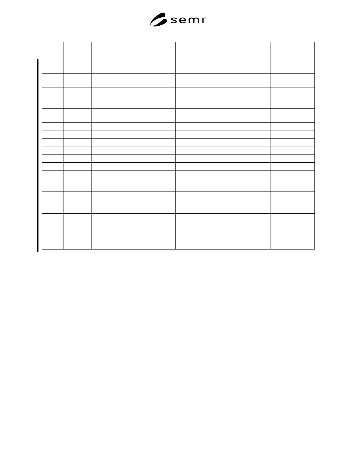
Symbol
Used
Shown In Datum Measured From Boundary or Feature Measured To Algebraic
Relation or Value
y9 Figure 2 facial datum plane outside edge of cassette top and bottom
plate domain
≤ L * 1.21
y10 Figure 3 facial datum plane inside edge of cassette top and bottom
plate indent
≤ L * 0.985
y11 Figure 3 facial datum plane inside edge of cassette sensing pad areas ≥ L * 0.708
y12 Figure 3 facial datum plane outside edge of cassette sensing pad
areas
≤ L * 0.954
y13 Figure 3 facial datum plane center of coupling exclusion zones
= L * 0.923 ±
0.1 mm
z1 Figure 4 horizontal datum plane bottom of cassette bottom domain
≥ 2 mm
z2 Figure 4 horizontal datum plane bottom of cassette sensing pads
= 3 ± 0.5 mm
z3 Figure 6 horizontal datum plane bottom surface of conveying surface
= 2 ± 0.5 mm
z4 Figure 4 horizontal datum plane top of cassette bottom domain
≤ 40 mm
z5 Figure 4 horizontal datum plane bottom nominal substrate seating plane = 60 mm
z6 Figure 4 each nominal substrate seating plane bottom of substrate
= ± 0.5 mm
z7 Figure 4 each nominal substrate seating plane encroachment of cassette side domains
on clearance above the substrate
See Table 4.
z8 Figure 4 each nominal substrate seating plane adjacent nominal substrate seating planes See Table 4.
z9 Figure 4 top nominal substrate seating plane bottom of cassette top domain
≥ z7 + 1 mm
z10 Figure 4 top nominal substrate seating plane bottom of clearance under robotic
handling flange
≤ 30 mm
z11 Figure 4 top nominal substrate seating plane top of clearance under robotic handling
flange
= 40 ± 1 mm
z12 Figure 4 top nominal substrate seating plane top of top cassette domain
≤ 50 mm
z14 Figure 6 horizontal datum plane top of v-rail, v-groove, and float roller
exclusion zones
= 24.86 ±
0.12 mm