semi合集-English.pdf - 第706页
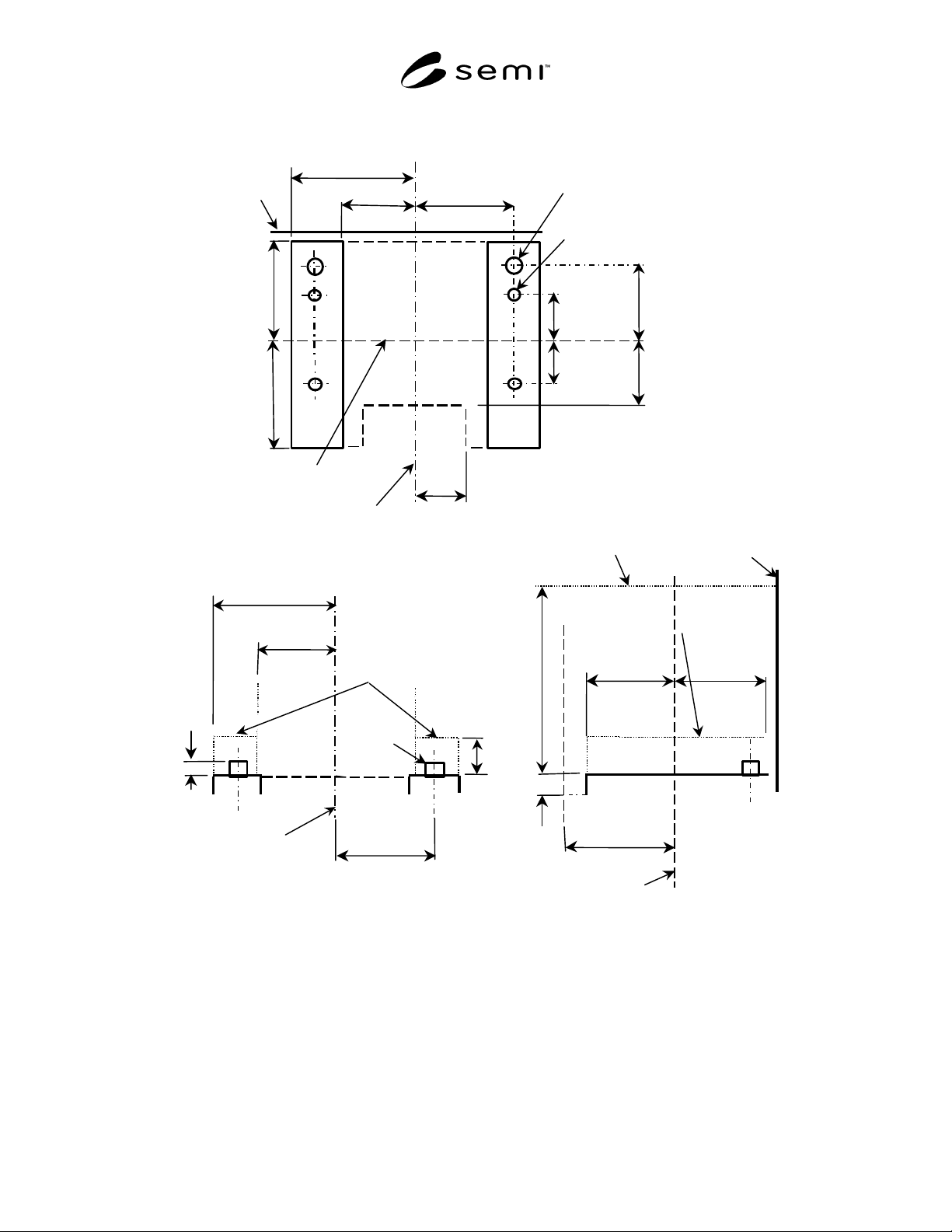
SEMI E92-0302 E © SEMI 1999, 2003 9 Positio ning Pin BOLTS/ Light Plane Anti-rotation Pin TOP VIEW Figure 4 Usage of Loader Locating Pins Table 1 Dimensions for Light-Weight and Compact Box Opener/Load er to Tool Standar…
SEMI E92-0302
E
© SEMI 1999, 2003 8
Top View
Facial datum plane
(Undock position)
Bilateral
datum plane
Front View
Side View
Horizontal
datum plane
z110
=10 ±1
z112
≥
15
z107
=480 ±1
ISO M8x16H
Thread for locking screws (4x)
d1=12 ±0.05(PIN 2x)
y106
=180 ±0.05
y109
=110 +0/-5
y107
=100 ±0.3
y108
=100 ±0.3
Seal zone
y104
=200 +0/-10
y105
=220 +0/-10
x104=235 ±2
x105=200 ±2
x106
=220 ±0.05
x107
=175 +5/-0
[E15.1_D]
Facial datum plane
(Undock position)
Bilateral
datum plane
d1=12 ±0.05(PIN 2x)
x106
=220 ±0.05
y105
=220 ±10
x108
= 207±1
x109
≥
235
y115
≥
220
z113
≥
30
y116
≥
200
Seal zone
the loader
bottom flange
exclusion volume
the loader bottom
flange exclusion volume
Figure 3
Equipment Side of the Bottom Interface Feature
SEMI E92-0302
E
© SEMI 1999, 2003 9
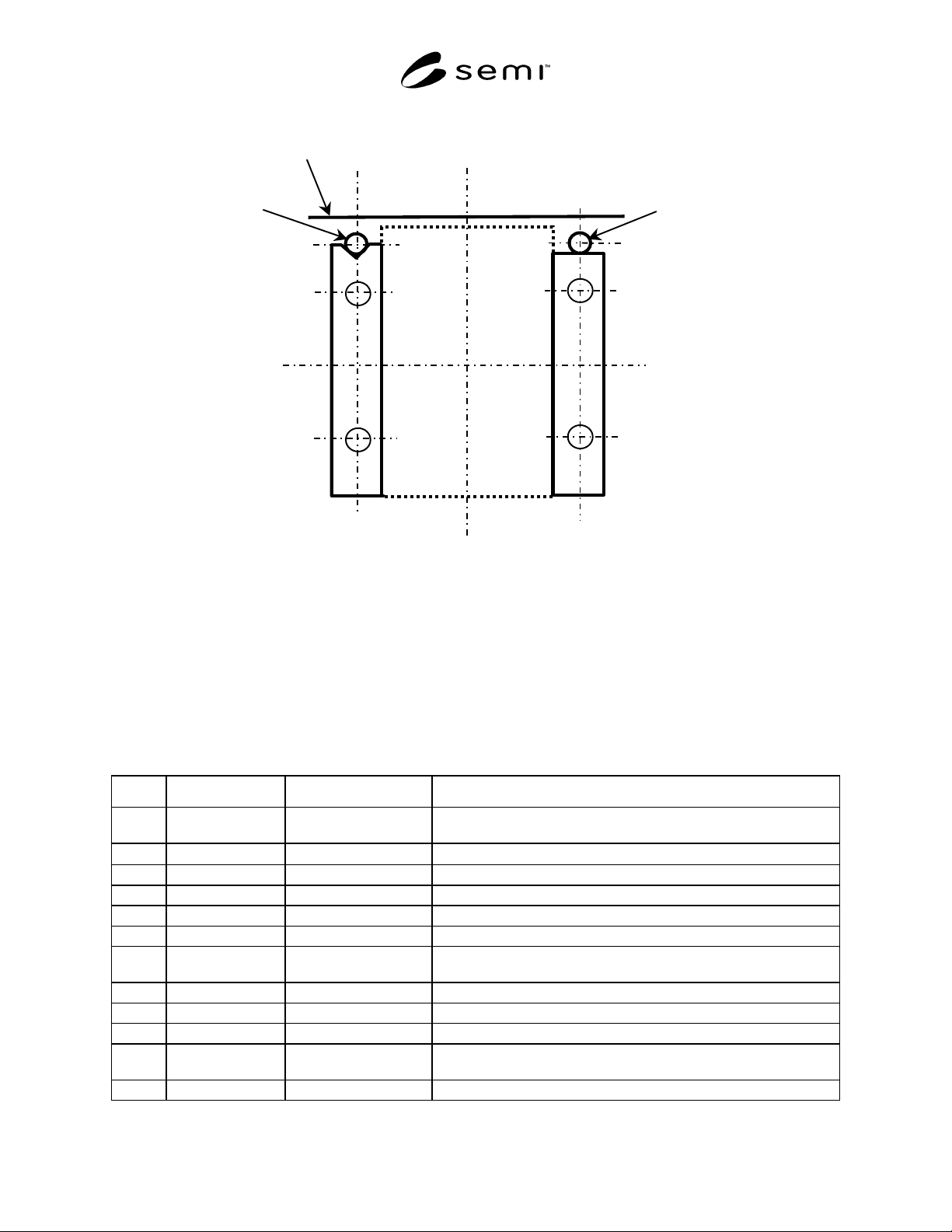
Positioning
Pin
BOLTS/Light Plane
Anti-rotation
Pin
TOP VIEW
Figure 4
Usage of Loader Locating Pins
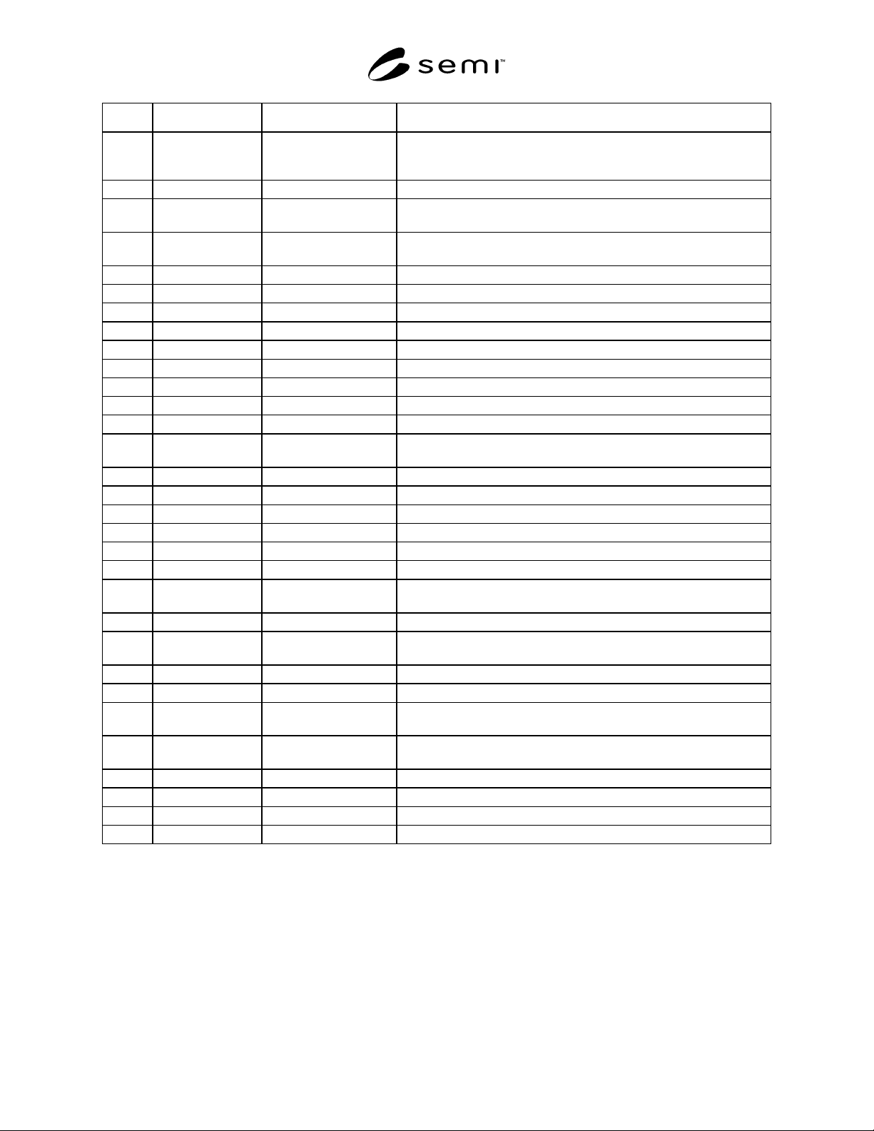
Table 1 Dimensions for Light-Weight and Compact Box Opener/Loader to Tool Standard (BOLTS/Light)
Interface
Symbol Value Specified Datum Measured from Feature Measured to
σ1
0 ± 0.1° Facial and horizontal
datum planes
Perpendicularity of seal zone.
σ2
0 ± 0.1° Horizontal datum plane Parallelism of bottom interface plane.
d1 12 ± 0.05 mm - Loader locating pin diameter.
r100 1 mm maximum not applicable All concave features. (radius)
r101 2 mm maximum not applicable All required convex features. (radius)
x101 200 ± 1 mm Bilateral datum plane Edge of hole opening and inside edge of seal zone.
x102 199 mm minimum Bilateral datum plane Encroachment of equipment on the sides of the reserved spaces inside
the equipment.
x103 207 ± 1 mm Bilateral datum plane Outside edge of seal zone.
x104 235 ± 2 mm Bilateral datum plane Outside edge of bottom interface plane.
x105 200 ± 2 mm Bilateral datum plane Inside edge of bottom interface plane.
x106 220 ± 0.05 mm Bilateral datum plane Center of positioning pin location and tightening locking screw
location.
x107 175 +5/-0 mm Bilateral datum plane Outside edge of control connection area.
SEMI E92-0302
E
© SEMI 1999, 2003 10
Symbol Value Specified Datum Measured from Feature Measured to
x108 207 ± 1 mm Bilateral datum plane Width of the door seal exclusion volume.
Width of the loader exclusion volume.
Width of the loader bottom flange exclusion volume. (Inside)
x109 235 mm minimum Bilateral datum plane Width of the loader bottom flange exclusion volume. (Outside)
y101 170 ± 2 mm Docked Facial datum
plane
BOLTS/Light plane. Seal surface on equipment.
y102 80 mm minimum BOLTS/Light plane Encroachment of equipment on the permanent reserved space and on
the reserved space when the door is opening or closing.
y103 3 mm minimum BOLTS/Light plane Encroachment of equipment.
y104 200 + 0/-10 mm Facial datum plane Rear edge of bottom interface plane.
y105 220 + 0/-10 mm Facial datum plane Front edge of bottom interface plane.
y106 180 ± 0.05 mm Facial datum plane Positioning pin location.
y107 100 ± 0.3 mm Facial datum plane Front locking screw location.
y108 100 ± 0.3 mm Facial datum plane Rear locking screw location.
y109 110 + 0/-5 mm Facial datum plane Rear edge of control connection area.
y110 [E63] Facial datum plane Docked-facial datum plane.
y111 220 ± 2 mm Facial datum plane Front end of the loader exclusion volume.
y112 31 mm minimum BOLTS/Light plane Encroachment of equipment on the reserved space when the door is
closed.
y113 ± 0.5 mm - Cycle-to-cycle repeatability of y101.
y114 ± 1 mm - Flatness of seal zone.
y115 220 mm minimum Facial datum plane Front face of the loader bottom flange exclusion volume.
y116 200 mm minimum Facial datum plane Rear face of the loader bottom flange exclusion volume.
z101 402 ± 1 mm Horizontal datum plane Outside edge of seal zone on top.
z102 478 ± 1 mm Horizontal datum plane Outside edge of seal zone on bottom.
z103 394 mm minimum Horizontal datum plane Encroachment of equipment on the top of the permanent reserved
space inside the equipment.
z104 395 ± 1 mm Horizontal datum plane Top edge of hole opening and inside edge of seal zone.
z105 470 mm minimum Horizontal datum plane Encroachment of equipment on the bottom of the permanent reserved
space inside the equipment.
z106 471 ± 1 mm Horizontal datum plane Bottom edge of hole opening and inside edge of seal zone.
z107 480 ± 1 mm Horizontal datum plane Height of the bottom interface planes.
z108 45 ± 2 mm Horizontal datum plane Encroachment of equipment on the top of the permanent reserved
space inside the equipment.
z109 402 ± 2 mm Horizontal datum plane Encroachment of equipment on the top of the box opener/ loader
between the BOLTS/Light plane and the SEMI E15.1_D1 plane.
z110 10 ± 1 mm Bottom end of z107 locating pins height.
z111 45 ± 2 mm Horizontal datum plane Panel Interface Height.
z112 15 mm minimum Bottom end of z107 Docking space to bottom interface plane during maintenance.
z113 30 mm minimum Bottom end of z107 Height of loader bottom flange exclusion volume.