semi合集-English.pdf - 第6911页
SEMI S8-0705 © SEMI 1995, 2005 8 Grether W.F. and Baker C.A., 1972, Visual P resentation of Informati on in Van Cott and Kincade Hu man Engineering t o Equipme nt Design, Washi ngton DC, US Governm ent Printing Office. K…

SEMI S8-0705 © SEMI 1995, 2005 7
7.4 The evaluation should specify an installation reference point for each independently adjustable section of the
equipment for vertical measures. If there is a supplier recommended installation height, the reference for the
evaluation should be the same. This installation height should be included in the supplier’s installation
documentation.
NOTE 3: Installation documentation may include installation manuals and other information provided by supplier addressing
installation concerns.
8 Related Documents
8.1 SEMI Standard
SEMI S13 — Safety Guidelines for Operation and Maintenance Manuals Used with Semiconductor Manufacturing
Equipment
8.2 ANSI Documents
ANSI Z535.4 — Product Safety Signs and Labels
8.3 CEN/CENELEC Standards
6
EN 614-1 — Safety of Machinery — Ergonomic Design Principles, Part 1. Terminology and General Principles
EN 894-1 — Safety/Ergonomics for Operator Interaction
EN 50099-2 — Safety/Marking Principles
8.4 NIOSH Documents
7
NIOSH Publication No. 81-122 — Work Practices Guide for Manual Lifting, National Institute for Occupational
Safety and Health, 1981.
Revised NIOSH Equation, Ergonomics, Vol. 36, No. 7, 1993.
8.5 SAE Document
8
SAE J833 — Human Physical Dimensions
8.6 SEMATECH Documents
9
Preventing User-Hostile Interfaces in IC-Fab Equipment — Ergonomic Approaches for Preventing Ten Frequent
Interface Problems, Miller, Dwight P. and Whitehurst, Hugh,
SEMATECH Technology Transfer #92091299NA-
ENG, Nov. 1992.
SEMATECH SCC User interface Style Guide, 1.0. 92061179A-ENG, August 21, 1992.
8.7 Other Documents
Bailey, Robert W., Human Performance Engineering, Prentice Hall, 1989.
Eastman Kodak Company, Ergonomic Design for People at Work, Vols. 1 and 2, Van Nostrand-Reinhold, 1983.
EN ISO 7250 — Basic human body measurements for technological design
EN ISO 14738 — Safety of Machinery, Anthropometric requirements for the design of workstations at machinery
Grandjean, E., Fitting the Task to the Man: A Textbook of Occupational Ergonomics (4th Ed.), Taylor & Francis,
1988.
6 European Committee for Standardization (CEN)/European Committee for Electrotechnical Standardization (CENELEC), Central Secretariat,
rue de Stassart 35, B-1050 Brussels, Belgium, Website: www.cenelec.com.
7 National Institute for Occupational Safety and Health, Technical Information Branch, 4676 Columbia Pkwy, Cincinnati, OH 45226. Website:
www.niosh.com.my.
8 Society of Automotive Engineers, 400 Commonwealth Drive, Warrendale, PA 15096 USA. Website: www.sae.org.
9 International SEMATECH, 2706 Montopolis Drive, Austin, TX 78741, USA., Website: www.sematech.org

SEMI S8-0705 © SEMI 1995, 2005 8
Grether W.F. and Baker C.A., 1972, Visual Presentation of Information in Van Cott and Kincade Human
Engineering to Equipment Design, Washington DC, US Government Printing Office.
Konz, S., Work Design: Industrial Ergonomics (3rd Ed), Publishing Horizons, 1990.
Pheasant, Stephen, Bodyspace — Anthropometry, Ergonomics and Design, Taylor & Francis, 1988.
Salvendy, Gavriel (ed.), Handbook of Human Factors, Wiley, 1987.
Sanders, Mark S. and McCormick, Ernest, Human Factors in Engineering and Design (7th Ed), McGraw-Hill Book
Company, 1993.
Snook, Stover and V. Ciriello, The Design of Manual Handling Tasks — Revised Tables of Maximum Acceptable
Weights and Forces, Ergonomics, Vol. 34, No. 9, 1991.
VanCott, Harold P. and Kinkade, Robert (eds.), Human Engineering Guide to Equipment Design, U. S. Government
Printing Office, 1972.
NOTICE: Unless otherwise indicated, all documents cited shall be the latest published versions.
SEMI S8-0705 © SEMI 1995, 2005 9
APPENDIX 1
SUPPLIER ERGONOMIC SUCCESS CRITERIA (SESC)
NOTICE: The material in this appendix is an official part of SEMI S8 and was approved by full letter ballot
procedures by the North American Regional Standards Committee.
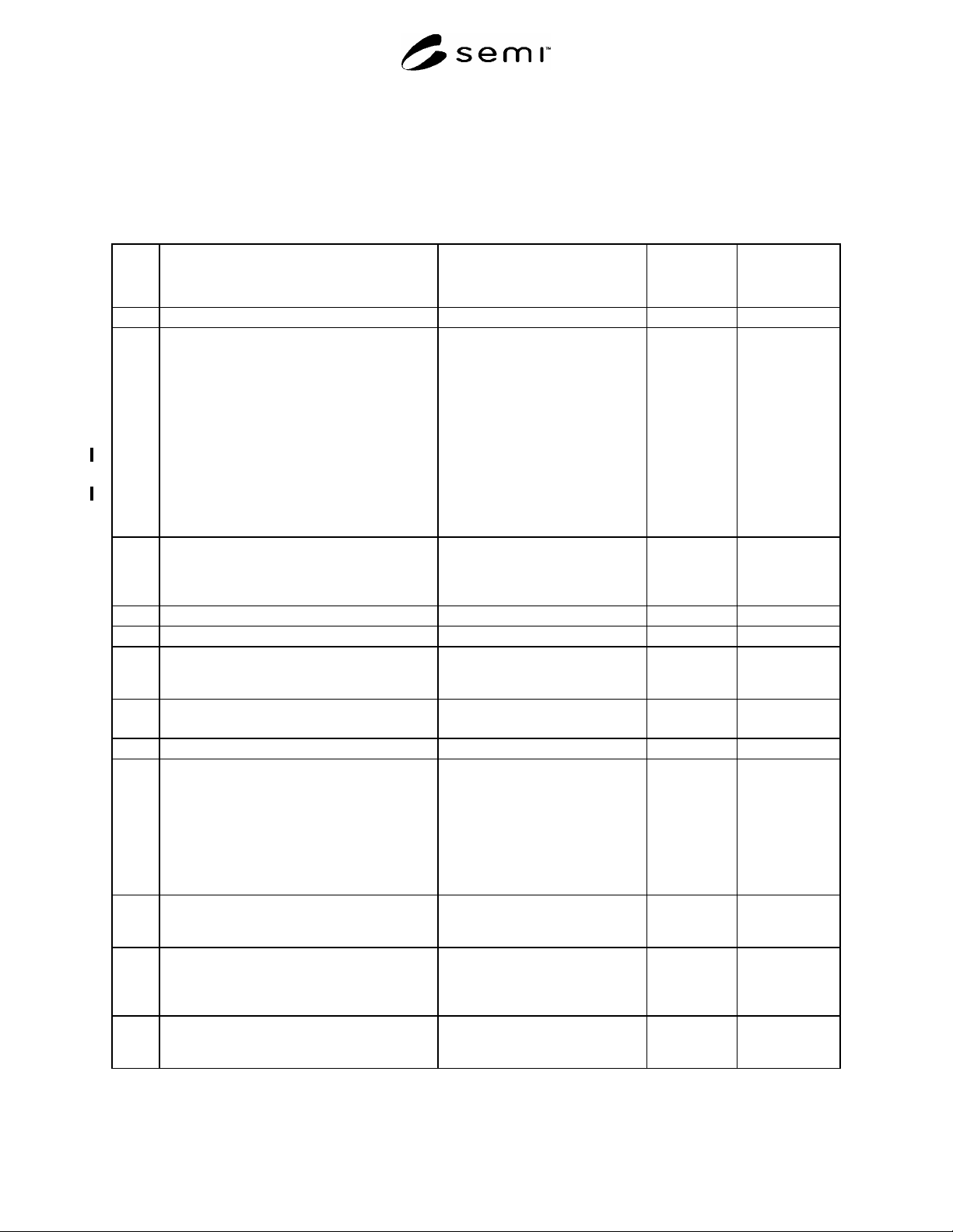
Table A1-1 Supplier Ergonomic Success Criteria Checklist
Section Indicator
Acceptance Criteria
Metric Units (US Customary Units)
Actual
Conforms/Does
N
ot Conform/Not
Applicable
1 Manual Material Handling
1.1 Potentially hazardous manual material handling
tasks performed as part of operations,
maintenance, or service are analyzed utilizing
appropriate procedures.
NOTE: Two hand lifting or lowering tasks
should be analyzed:
if the object being handled weighs more than
44.5 N (10 lbf);
OR, if the object weighs more than 22.2 N
(5 lbf) and the anticipated frequency is greater
than 1 lift every 5 minutes.
See Appendix 2 for further information.
Analysis and results
documentation. Table A2-2,
Appendix 2, or the equivalent,
should be used to document 2 hand
lift/lower analysis.
2 Product Loading in a Standing Posture
(Applicable to all media other than wafer
cassettes including JEDEC trays, magazines,
and reticle cassettes.
2.1 Clearance provided for finger thickness. minimum 38 mm (1.5 in.)
2.2 Clearance provided for hand thickness. minimum 76 mm (3.0 in.)
2.3 Reach distance measured from the leading edge
of the tool or obstruction to the hand/product
coupling point(s).
maximum 330 mm (13 in.)
2.4 Vertical coupling point of hand to product in
load position
maximum 1010 mm (40 in.)
minimum 890 mm (35 in.)
3 Wafer Cassette Loading
3.1 Wafer cassette loading should not require
greater than 10 degrees cassette rotation in any
axis.
NOTE: Unless otherwise specified, you should
assume that 200 mm or smaller wafers are
transported in the vertical orientation and that
300 mm wafers are transported in the horizontal
orientation.
less than 10 degrees rotation in any
axis
3.2 Load port height, vertical distance from
standing surface
(150–200 mm wafers).
maximum 960 mm (38 in.)
minimum 890 mm (35 in.)
3.3 Maximum lip height in front of cassette load
port over which cassette is lifted (150–200 mm
wafer cassettes only). Measure lip height from
the load surface.
maximum 30 mm (1.2 in.)
3.4 Reach distance from the leading edge of the tool
or obstruction to the coupling point(s) on
rotation device or the product grasp point.
maximum 330 mm (13 in.)