semi合集-English.pdf - 第5481页
SEMI P3-0298 © SE MI 1982, 1998 1 SEMI P3-0298 SPECIFICA TION FOR PHOTORESIST/E-BEAM RESIST FOR HARD SURFACE PHOTOPLATES 1 Purpose 1.1 This s p ecification covers the g e n era l requirements on t he ph otoresist and e-b…
SEMI P2-0298 © SEMI 1981, 1998 2
material was manufactured and tested shall be in
accordance with this specification.
11 Packing and Marking
11.1 Substrates shall be packed in a Class 100
environment. Containers shall be designed to prevent
glass-to-glass contact and to protect the substrates from
contamination in handling and transit. Substrates shall
be shipped with the coated side facing toward the same
end of the box. This orientation shall be indicated on
each container. Packaging shall comply with the
applicable international, national, state laws, and local
regulations required for shipping.
11.2 Containers shall be labeled, “Warning: Open and
Handle Under Clean Room Conditions Only.” Each
shipment shall be identified by user purchase order
number, drawing number (if applicable), quantity,
supplier lot number, and material identification.
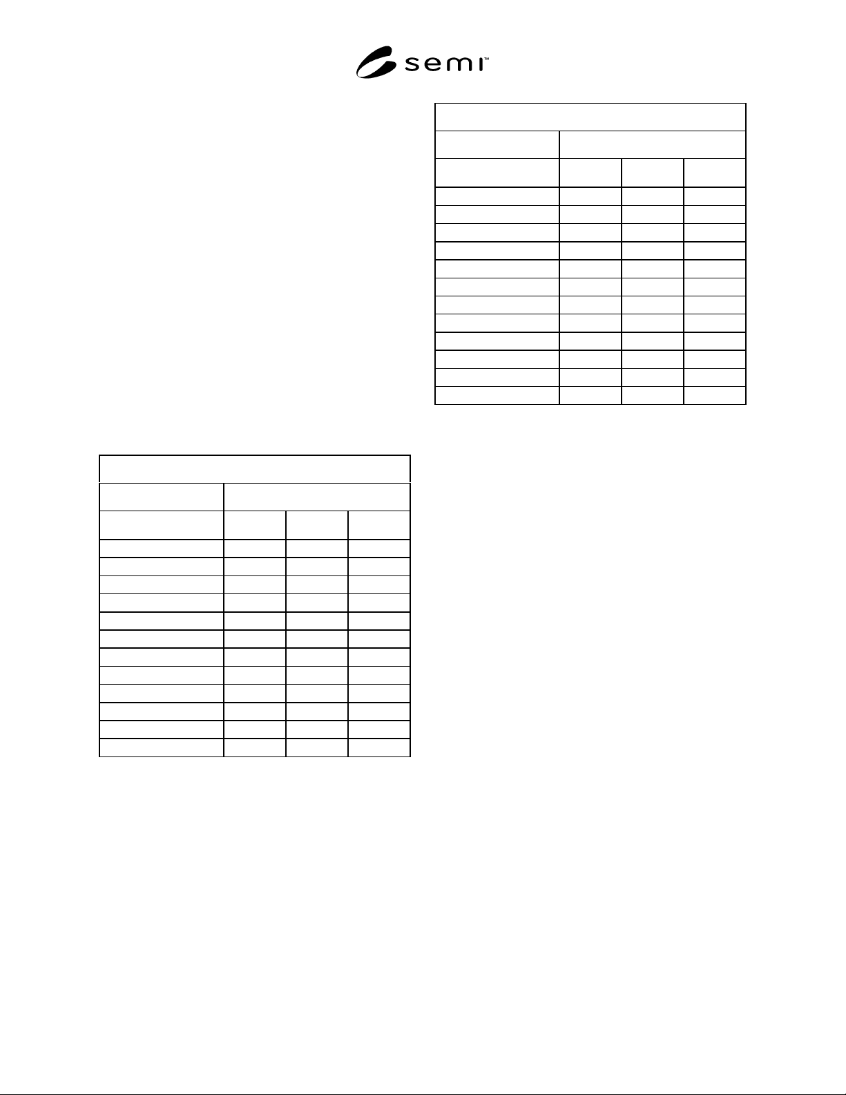
Table 1 Total Allowable Defects for Unsensitized
Photoplates
Defects in the Circular Quality Area
Substrate Size Defect Size
Grade
1–5.0
µ
m 5.1–10
µ
m 10
µ
m
4" AA 000
4" A (Master) 2 0 0
4" B 310
4" C (Test) N/A N/A 10
5" AA 000
5" A (Master) 2 0 0
5" B 410
5" C (Test) N/A N/A 15
6" AA 000
6" A (Master) 3 0 0
6" B 620
6" C (Test) N/A N/A 20
Defects in the Square Quality Area
Substrate Size Defect Size
Grade
1–5.0
µ
m 5.1–10
µ
m 10
µ
m
4" AA 000
4" A (Master) 2 0 0
4" B 410
4" C (Test) N/A N/A 10
5" AA 000
5" A (Master) 3 0 0
5" B 620
5" C (Test) N/A N/A 15
6" AA 000
6" A (Master) 4 0 0
6" B 820
6" C (Test) N/A N/A 20
NOTICE: These standards do not purport to address
safety issues, if any, associated with their use. It is the
responsibility of the user of these standards to establish
appropriate safety and health practices and determine
the applicability of regulatory limitations prior to use.
SEMI makes no warranties or representations as to the
suitability of the standards set forth herein for any
particular application. The determination of the
suitability of the standard is solely the responsibility of
the user. Users are cautioned to refer to manufacturer’s
instructions, product labels, product data sheets, and
other relevant literature respecting any materials
mentioned herein. These standards are subject to
change without notice.
The user’s attention is called to the possibility that
compliance with this standard may require use of
copyrighted material or of an invention covered by
patent rights. By publication of this standard, SEMI
takes no position respecting the validity of any patent
rights or copyrights asserted in connection with any
item mentioned in this standard. Users of this standard
are expressly advised that determination of any such
patent rights or copyrights, and the risk of infringement
of such rights, are entirely their own responsibility.
Copyright by SEMI® (Semiconductor Equipment and Materials
International), 3081 Zanker Road, San Jose, CA 95134. Reproduction o
f
the contents in whole or in part is forbidden without express written
consent of SEMI.

SEMI P3-0298 © SEMI 1982, 19981
SEMI P3-0298
SPECIFICATION FOR PHOTORESIST/E-BEAM RESIST FOR HARD
SURFACE PHOTOPLATES
1 Purpose
1.1 This specification covers the general requirements
on the photoresist and e-beam resist coating for hard
surface photoplates. See SEMI P1 and SEMI P2 for
requirements on physical characteristics of the
photoplate substrate and the chrome coating on it.
2 Referenced Documents
2.1 SEMI Specifications
SEMI P1 — Specification for Hard Surface Photomask
Substrates
SEMI P2 — Specification for Chrome Thin Films for
Hard Surface Photomasks
2.2 ASTM Standard
1
ASTM E 122 — Recommended Practice for Choice of
Sample Size to Estimate the Average Quality of a Lot
or Process
2.3 Federal Standard
2
209D — Clean Room and Work Station Requirements,
Controlled Environments
2.4 Military Specification
3
MIL-STD-105 — Sampling Procedure and Tables for
Inspection and Attributes
3 Terminology
3.1 comets — buildup of resist in the form of a comet,
generated by a defect.
3.2 defect, photomask — any flaw or imperfection in
the opaque coating or functional pattern of a photomask
that will reproduce itself in a photoresist film to such a
degree that it is pernicious to the proper functioning of
the microelectric device being fabricated.
3.3 fingerprint — for the purposes of this practice,
residual surface contamination deposited during
handling.
1 American Society for Testing and Materials, 100 Barr Harbor
Drive, West Conshohoken, PA 19428-2959
2 General Services Administrator, 4th and D Streets, SW, Room
6039, Washington, D.C. 20407
3 Military Standards, Naval Publication and Form Center, 5801 Tabor
Avenue, Philadelphia, PA 19120
3.4 photoresist lifting — the loss of adhesion of a
photoresist coating to its substrate.
3.5 pinhole — a small opening extending through a
cover as a photoresist coating or an oxide layer.
3.6 residue — any undesirable material remaining on
a substrate after any process step.
3.7 resist rings — buildup of resist in round,
multicolored rings, generated by particles or bubble
bursts.
3.8 stress marks — radial, colored, thin lines starting
in the center of the plate and extending out.
4 Ordering Information
4.1 Purchase orders for resist-coating for hard surface
photoplate substrates furnished to this specification
shall include the following in addition to the
information called for in SEMI P1 and SEMI P2:
4.1.1 Resist Material
4.1.2 Resist Thickness and Tolerance in the Quality
Area
4.1.3 Resist Uniformity across the Quality Area
4.1.4 Resist Consistency — from Plate to Plate
4.1.5 Resist Baking Time and Temperature
5 Visual Criteria
5.1 Visual Quality Area
5.1.1 Circular Visual Quality Area — (See SEMI P1,
Figure 6, for Available Flatness Limits of Hard Surface
Photomask Substrates.)
5.1.2 Square Visual Quality Area — (See SEMI P1,
Figure 7, for Available Flatness Limits of Hard Surface
Photomask Substrates.)
6 Defects
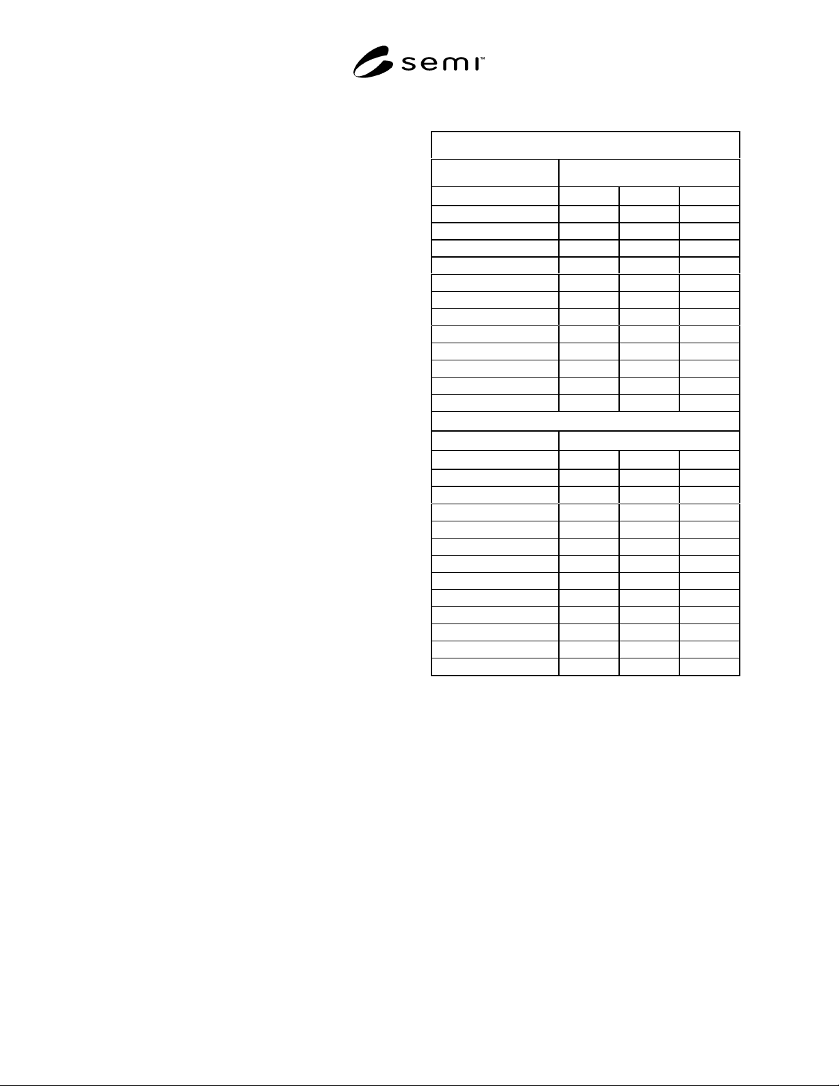
6.1 Definitions of defects and the allowable number of
each type are noted in Table 1. The number of defects is
indicated by plate size, chrome grades, and defect size.
7 Sampling
7.1 Unless otherwise specified, Recommended Practice
ASTM E 122 shall be used. When so specified,
appropriate sample sizes shall be selected from each lot
in accordance with MIL-STD-105. Each quality
SEMI P3-0298 © SEMI 1982, 1998 2
characteristic shall be assigned an acceptable quality
level (AQL) and lot total percent defective (LTPD)
value in accordance with MIL-STD-105. Definitions
for critical, major, and minor classifications may
alternatively be assigned cumulative AQL and LTPD
values. Inspection levels shall be agreed upon between
the user and supplier.
8 Handling
8.1 Resist-coated substrates are to be handled on the
edges only with approved finger cots or gloves under
clean room conditions.
9 Certification
9.1 Upon request of the purchaser in the contract or
order, a manufacturer’s or supplier's certification that
the material was manufactured and tested in accordance
with this specification shall be provided.
10 Packaging and Marking
10.1 Resist-coated substrates shall be packed in a
Class 100 environment as defined in Federal Standard
209D. Containers shall be designed to prevent
movement and glass-to-glass contact and to protect the
substrates from contamination in handling and transit.
Orientation of the coated side shall be indicated on each
container. Packaging shall comply with the applicable
international, national, state, and local laws and
regulations required for shipping.
10.2 Each shipment shall be identified by user
purchase order number, drawing number (if applicable),
quantity, supplier lot number, material identification,
bake time and temperature, resist type, resist lot
number, and date of applying resist.
10.2.1 Photoresist — Containers shall be labeled,
“Warning: Open and Handle Under Safe Yellow Light
in Clean Room Conditions Only.”
10.2.2 E-Beam Resist — Containers shall be labeled,
“Warning: Open and Handle Under Clean Room
Conditions Only. DO NOT X-RAY.”
Table 1 Total Allowable Defects for Unsensitized
Photoplates
Defects in the Circular Quality Area
Substrate Size Defect Size
Grade
1–5.0 µm5.1–10 µm 10 µm
4" AA 0 0 0
4" A (Master) 4 0 0
4" B 6 2 0
4" C (Test) N/A N/A 20
5" AA 0 0 0
5" A (Master) 4 0 0
5" B 8 2 0
5" C (Test) N/A N/A 30
6" AA 0 0 0
6" A (Master) 6 0 0
6" B 12 4 0
6" C (Test) N/A N/A 40
Defects in the Square Quality Area
Substrate Size Defect Size
Grade
1–5.0 µm5.1–10 µm 10 µm
4" AA 0 0 0
4" A (Master) 4 0 0
4" B 8 2 0
4" C (Test) N/A N/A 20
5" AA 0 0 0
5" A (Master) 6 0 0
5" B 12 4 0
5" C (Test) N/A N/A 30
6" AA 0 0 0
6" A (Master) 8 0 0
6" B 16 2 0
6" C (Test) N/A N/A 40