semi合集-English.pdf - 第6086页
SEMI G14-88 © SEMI 198 2, 1996 4 NOTICE: T hese standards do n ot purport to address safety issues, if any, ass o ciated with their use. It is the responsibility of t he user of these standards to establish appropriate s…
SEMI G14-88 © SEMI 1982, 19963
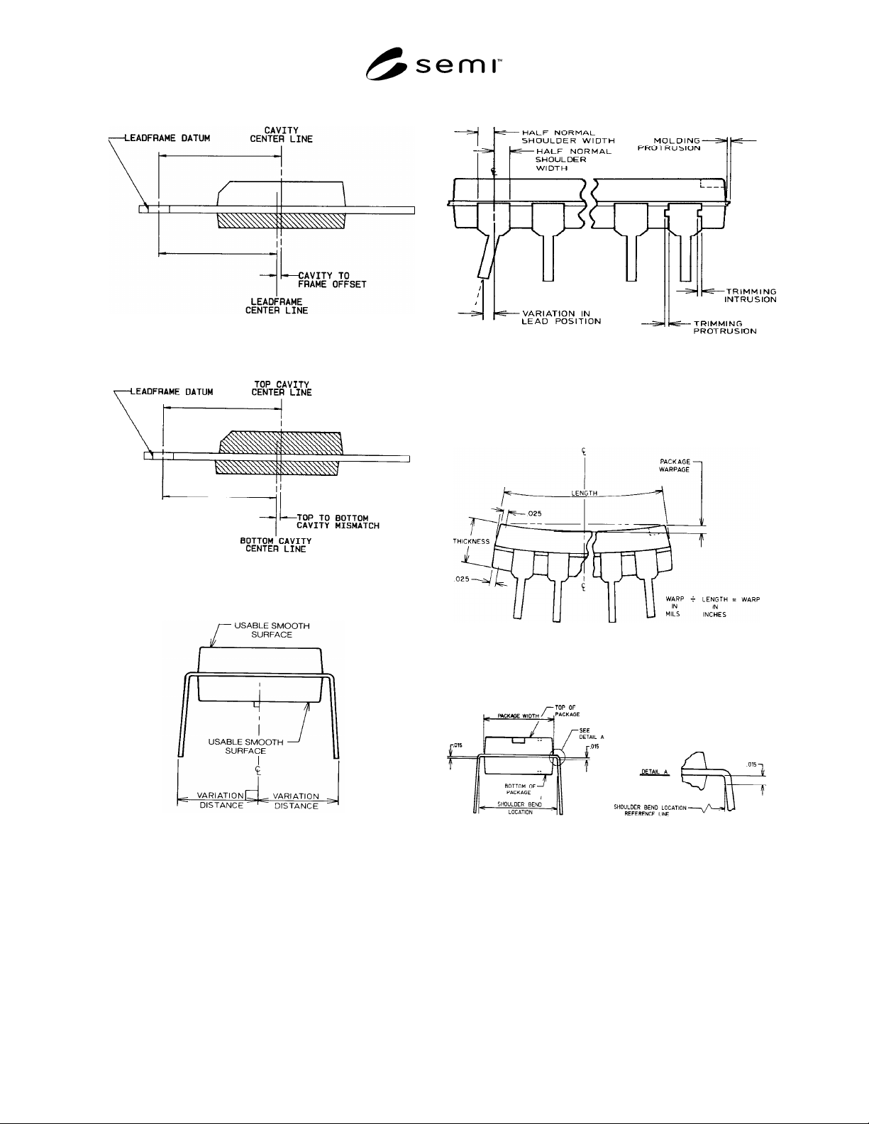
Figure 1
Figure 2
Figure 3
Variations from Nominal Lead Location
Figure 4
Parting Line Protrusions and Variation in Lead
Position
Figure 5
Package Warpage and Thickness
Figure 6
Shoulder Bend Location and Package Width

SEMI G14-88 © SEMI 1982, 1996 4
NOTICE: These standards do not purport to address
safety issues, if any, associated with their use. It is the
responsibility of the user of these standards to establish
appropriate safety and health practices and determine
the applicability of regulatory limitations prior to use.
SEMI makes no warranties or representations as to the
suitability of the standards set forth herein for any
particular application. The determination of the
suitability of the standard is solely the responsibility of
the user. Users are cautioned to refer to manufacturer’s
instructions, product labels, product data sheets, and
other relevant literature respecting any materials
mentioned herein. These standards are subject to
change without notice.
The user’s attention is called to the possibility that
compliance with this standard may require use of
copyrighted material or of an invention covered by
patent rights. By publication of this standard, SEMI
takes no position respecting the validity of any patent
rights or copyrights asserted in connection with any
item mentioned in this standard. Users of this standard
are expressly advised that determination of any such
patent rights or copyrights, and the risk of infringement
of such rights, are entirely their own responsibility.
Copyright by SEMI® (Semiconductor Equipment and Materials
International), 3081 Zanker Road, San Jose, CA 95134. Reproduction o
f
the contents in whole or in part is forbidden without express written
consent of SEMI.

SEMI G15-93 © SEMI 1982, 19961
SEMI G15-93
STANDARD TEST METHOD FOR DIFFERENTIAL SCANNING
CALORIMETRY OF MOLDING COMPOUNDS
1 Preface
1.1 Scope — This document describes procedures for
evaluating epoxy molding compounds by differential
scanning calorimetry (DSC).
1.2 Units — This test method uses SI units.
2 Applicable Documents
2.1 Reference Documents
2.1.1 ASTM Specifications
1
ASTM E 793 — Test Method for Heats of Fusion and
Crystallization by Differential Scanning Calorimetry
ASTM E 967 — Practice for Temperature Calibration of
Differential Scanning Calorimeters and Differential
Thermal Analyzers
ASTM E 968 — Practice for Heat Flow Calibration of
Differential Scanning Calorimeters
2.2 Related Documents
2.2.1 ASTM Specifications
ASTM E 473 — Standard Definitions of Terms Relating
to Thermal Analyses
ASTM E 1269 — Test Method for Determining Specific
Heat by Differential Scanning Calorimetry
3 Significance
3.1 DSC provides a rapid method at incoming
inspection for evaluating molding compounds for
consistency in subsequent molding processes.
4 Interferences
4.1 Very small quantities of material are used in the
test. Lack of homogeneity may cause variable results.
4.2 Gas Purge — See Section 5.
4.3 Sample Pans — See Section 5.
5 Equipment
5.1 Differential Scanning Calorimeter — Capable of
heating a sample from room temperature to 300°C with
a controlled heating rate.
1 American Society for Testing and Materials, 100 Barr Harbor
Drive, West Conshohoken, PA 19428-2959
NOTE 1: Gas Purge Considerations — A reactive gas purge
affects the material under test. A gas must be chosen that
reflects the molding conditions normally used for that
material (i.e., air or nitrogen).
5.2 Sampling Pans for DSC Cell — (Aluminum with
crimping or hermetically sealed.) The pans must not be
reactive to the sample under test.
5.3 Process Controller — Capable of collecting,
calculating, and plotting the data resulting from the
calorimeter.
5.4 Analytical Balance — Accuracy 0.001 mg.
5.5 Tweezers and Microspatula
6 Sampling
6.1 When the method is used to evaluate incoming
molding materials, the sampling plan shall be agreed
between supplier and customer.
6.2 Powdered or granular molding compounds shall be
thoroughly mixed before sampling. If the compound is
supplied in a preform, a small section may be cut off
the preform with a blade.
7 Preparation of Samples
7.1 Protect samples from moisture absorption while
awaiting test.
8 Equipment Setup and Cal ibration
8.1 Temperature Calibration — (Refer to ASTM E
967.)
8.1.1 Follow the manufacturer's operating manual to
set up and run a calibration curve using indium
(Melting Point 156.6°C) (see Figure 1).