semi合集-English.pdf - 第7232页
SEMI MF154-0305 © SEMI 2003, 2005 6 Figure 25 Slip on a (111) Wafer Following 10-min Wright Etch, Full Wafer View Figure 26 Swirl Pattern Developed by Preferentially Etching a Czochralski Grown 10 to 20 ·cm Lapped Sili…
SEMI MF154-0305 © SEMI 2003, 2005 5
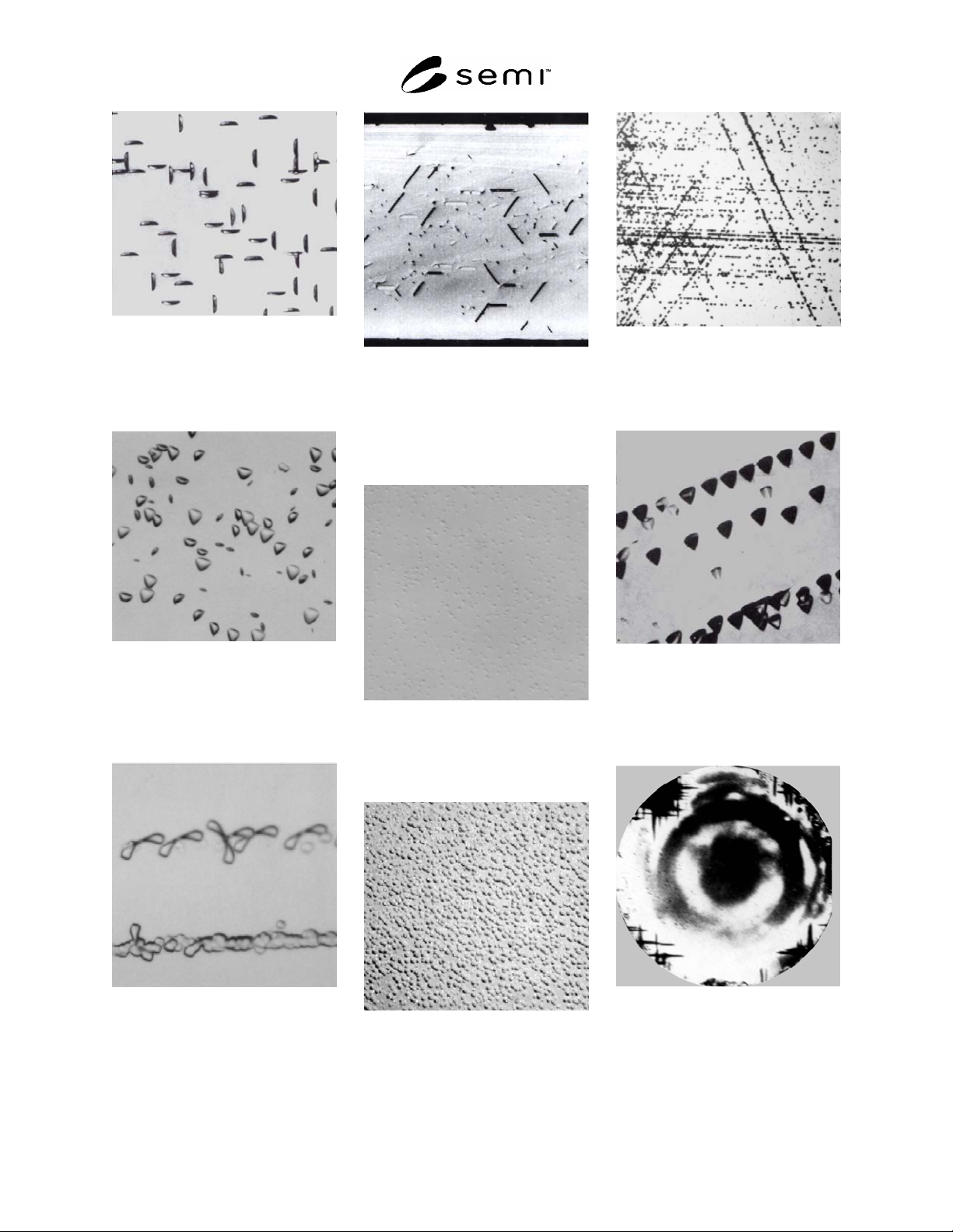
Figure 16
Oxidation Induced Stacking
Faults on (100) Silicon Following
Oxidation and 3-min Secco Etch,
Magnification 200×
Figure 17
Oxidation Induced Stacking
Faults on (111) Silicon Following
Oxidation and 4-min Wright
Etch, Magnification 200×
Figure 18
Oxidation Induced Stacking
Faults Caused by a Scratch on
(100) Silicon Following Oxidation
and 2-min Wright Etch,
Magnification 400×
Figure 19
Oxidation Induced Stacking
Faults and Precipitates Found on
the Cleavage Face of a Silicon
Wafer After Thermal Treatment
and 3-min Secco Etch,
Magnification 100×
Figure 20
Relatively Small Shallow Pits on
(111) Following Oxidation and
4-min Wright Etch,
Magnification 200×
Figure 21
Relatively Large Shallow Pits on
(111) Following Oxidation and
4-min Wright Etch,
Magnification 200×
Figure 22
Slip on a (111) Preferentially
Etched Wafer, Magnification 5×
Figure 23
Slip on a (111) Preferentially
Etched Wafer, Magnification
140×
Figure 24
Slip Lines on a (100) Wafer
Visible as a Cross Hatched
Pattern Near the Edge Because
Shallow Pits are Gettered
Following Oxidation and 4-min
Wright Etch
SEMI MF154-0305 © SEMI 2003, 2005 6
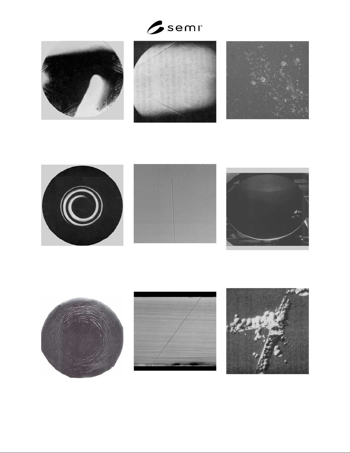
Figure 25
Slip on a (111) Wafer Following
10-min Wright Etch, Full Wafer
View
Figure 26
Swirl Pattern Developed by
Preferentially Etching a
Czochralski Grown
10 to 20
·cm
Lapped Silicon Wafer
Figure 27
A-swirl on As-grown Float-zone
Silicon Following Preferential
Etch, Full Wafer View
Figure 28
Twin Lines in a (111) Wafer after
Preferential Etching, Full Wafer
View
Figure 29
Twin Line Following 6.5
m
Epitaxial Deposition, No Other
Sample Preparation Required,
Magnification 300×
Figure 30
Twin Lamella in a <110> Cleaved
Vertical Cross Section Following
2.6
m Removal
in Leo (Modified Sirtl) Etch
Figure 31
Area Contamination,
Magnification 100×
Figure 32
Area Contamination Seen With a
High Intensity Light Source, Full
Wafer View
Figure 33
Crack, Resulting from the
Impact on the Wafer Surface,
Following Preferential Etch,
Magnification 450×
SEMI MF154-0305 © SEMI 2003, 2005 7
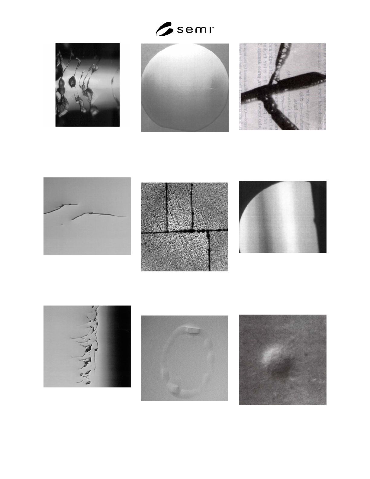
Figure 34
Crack on the Wafer Edge Due to
Mechanical Contact, No
Preparation Required,
Magnification 100×
Figure 35
Crack on a Wafer Surface Due to
Mechanical Contact, No
Preparation Required,
Magnification 750×
Figure 36
Crack Near the Edge of a Wafer
Surface Due to Mechanical
Contact, No Preparation
Required, Magnification 750×
Figure 37
Cracks in a Wafer Surface
Viewed with High Intensity Light
Exhibiting a Scratch-Like
Appearance
Figure 38
Cracks in an Etched Wafer
Surface, Magnification 38×
Figure 39
Crater, Usually Caused by
Inadequate Rinse of Polishing
Chemicals, Magnification 50×
Figure 40
“Crows-Foot” Crack Resulting
from the Impact of a Hard
Object with the Wafer
Highlighted by Preferential Etch,
Magnification 300×
Figure 41
Dimples Under Fluorescent
Lighting Conditions Distort the
Reflected Image
Figure 42
Dimple, No Preparation
Required, Magnification 512×