semi合集-English.pdf - 第813页
SEMI E111-0305 © SEMI 2001, 2005 10 Figure 11 Exterior Bottom View of RSP150 RFI D PL ACEM ENT Z ONE Figure 12 Detail E: RFID Placement Z one
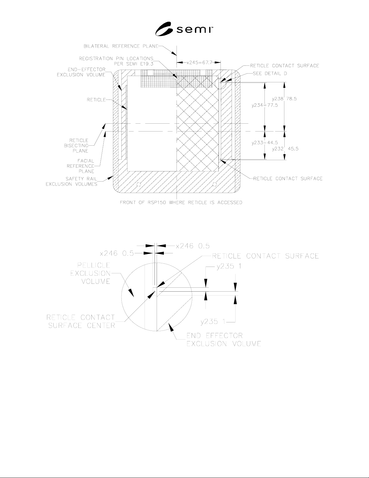
SEMI E111-0305 © SEMI 2001, 2005 9
Figure 9
Section B-B: Door Only Top View of RSP150 with Reticle Contact Surfaces
Figure 10
Detail D: Reticle Contact Surface
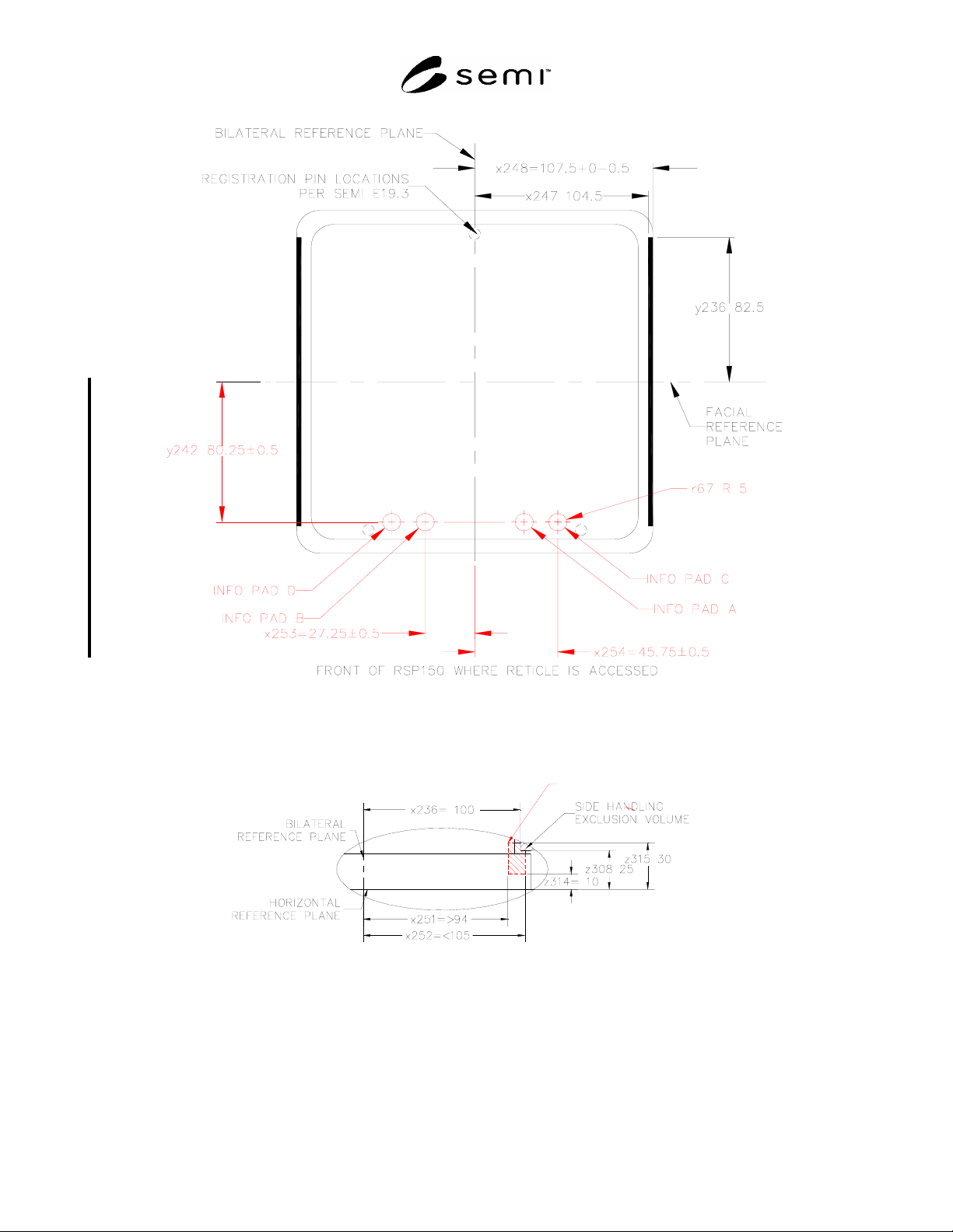
SEMI E111-0305 © SEMI 2001, 2005 10
Figure 11
Exterior Bottom View of RSP150
RFID PLACEMENT ZONE
Figure 12
Detail E: RFID Placement Zone
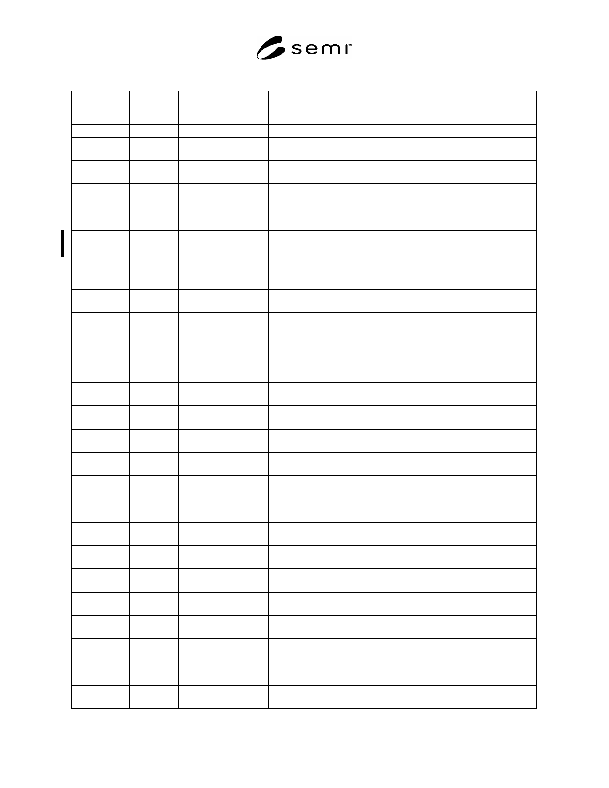
SEMI E111-0305 © SEMI 2001, 2005 11
Table 2 External and Internal Dimensions for RSP150
Symbol Used Figure Value Specified Reference Measured From Feature Measured To
1 45° ± 0.5° facial reference plane sides of orientation notches
1 45° ± 0.5° facial reference plane edge of side handling flange chamfer
2 45° ± 0.5° facial reference plane sides of side handling flange
orientation notches
5 45° ± 1° bilateral and facial plane
intersection
surface of the center hole in the top
robotic handling flange
r65 n/a 1 mm (0.039 in.)
maximum
not applicable all required concave features (radius)
r66 n/a 2 mm (0.079 in.)
maximum
not applicable all required convex features (radius)
r67 11 5 mm (0.197 in.)
minimum
info pad center perimeter of info pad
d63 5 35.0 + 0.9 / - 0.1 mm
(1.378 + 0.035 / -
0.004 in.)
centered on bilateral and
facial plane intersection
top robotic handling flange hole
design feature
x41 1 30 ± 1 mm
(1.181 ± 0.039 in.)
bilateral reference plane orientation notch center
x42 1 50 ± 1 mm
(1.969 ± 0.039 in.)
bilateral reference plane orientation notch center
x43 1 50 ± 1 mm
(1.969 ± 0.039 in.)
bilateral reference plane orientation notch center
x44 1 53 mm (2.087 in.)
maximum
bilateral reference plane side of robotic handling flange
column
x45 1 65.3 ± 1 mm
(2.571 ± 0.039 in.)
bilateral reference plane orientation notch tip
x46 1 71 ± 1 mm
(2.795 ± 0.039 in.)
bilateral reference plane edge of robotic handling flange
x47 1 58 mm (2.283 in.)
minimum
bilateral reference plane edge of robotic handling flange
corner beveling
x100 1 92.5 mm (3.642 in.)
minimum
bilateral reference plane edge of recess
x114 None 0 ± 1 mm
(0 ± 0.039 in.)
bilateral reference plane reticle bisecting plane
x119
4
65.2 mm (2.567 in.)
minimum
bilateral reference plane edge of pellicle exclusion volume
x129 2 5.68 ± 0.25 mm
(0.224 ± 0.010 in.)
side edge of side handling
flange
side handling flange alignment notch
tip
x223 1, 3 106.5 ± 1 mm
(4.193 ± 0.039 in.)
bilateral reference plane edge of side handling flange
x227 1 107.5 mm
(4.232 in.) maximum
bilateral reference plane side of pod
x236 3 100 mm (3.937 in.)
maximum
bilateral reference plane edge of side handling exclusion
volume
x238 4 68.2 mm (2.685 in.)
maximum
bilateral reference plane edge of end-effector exclusion
volume
x239 4 78.3 mm (3.083 in.)
maximum
bilateral reference plane edge of end-effector exclusion
volume
x240 4 85.3 mm (3.358 in.)
minimum
bilateral reference plane edge of end-effector exclusion
volume
x241 4 90 mm (3.543 in.)
maximum
bilateral reference plane edge of safety rail exclusion volume