semi合集-English.pdf - 第4100页
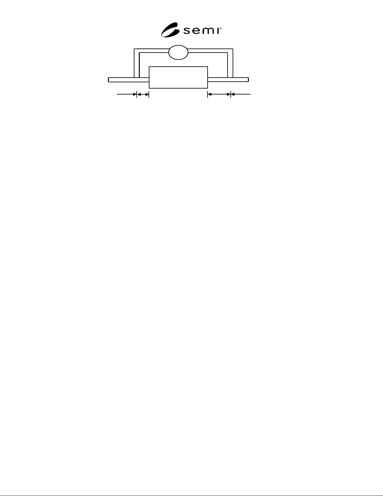
SEMI F59-0302 © SEMI 2000, 2002 6 Device Un der Test ∆ P A BC D A — A t least 16 nom inal pipe diame ters of str aight pipe. B — 2 Nom inal pipe diam eters of straight pipe . C — 6 Nom inal pipe diam eters of straight pi…
SEMI F59-0302 © SEMI 2000, 2002 5
15 Calculations or Interpretation of Results
15.1 Complete Tables 1–3 as needed for the DUT.
15.2 Graph the pressure drop versus the flow rate. An example of such a graph is shown in Figure 4 with separate
lines for different inlet pressure settings.
16 Precision and Accuracy
16.1 All measurements shall be recorded to the greatest precision allowed by the instruments unless accuracy in the
overall measurement is not affected by lower precision.
16.2 Accuracy of all instruments shall be recorded.
T1
Device Under
Test
DP
Regulating
Valve
Flow
Meter
Vent
Gas
Supply
(N
2
or CDA)
P1
Filter (optional)
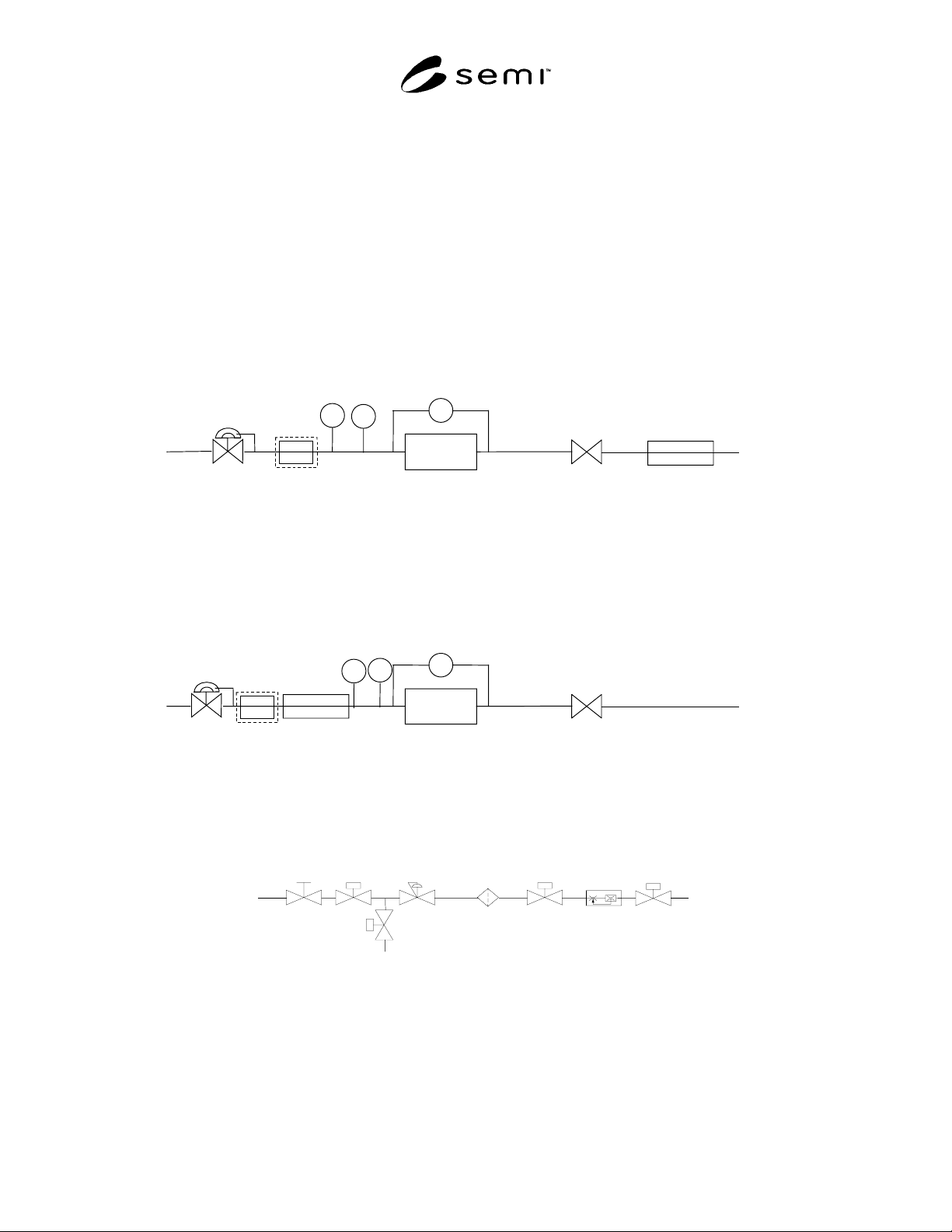
Figure 1a
Flow Pressure Drop Test Stand Schematic, Option 1
P1
Device Under
Test
DP
Regulating
Valve
Flow
Meter
Vent
Gas
Supply
(N
2
or CDA)
T1
Filter
(optional)
Figure 1b
FLow Pressure Drop Test Stand Schematic, Option 2
Figure 1c
Sample Gas System for Testing
SEMI F59-0302 © SEMI 2000, 2002 6
Device Under
Test
∆
P
A
BCD
A — At least 16 nominal pipe diameters of straight pipe.
B — 2 Nominal pipe diameters of straight pipe.
C — 6 Nominal pipe diameters of straight pipe.
D — At least 1 nominal pipe diameters of straight pipe
.
NOTE 1: Dimension “A” may be reduced to 8 nominal diameters if straightening vanes are used. Design of straightening vnes
can be found in ASME Performance Test Code PTC 19.5-1972, “Applications – Part 2 of “Fluid Meters, Interim Supplement on
Instruments and Apparatus.”
NOTE 2: If an upstream flow disturbance consists of two elbows in series and they are in different planes, dimension “A” must
exceed 16 nominal pipe diameters unless straightening vanes are used.
Figure 2
Piping Requirements – Standard Test Section
SEMI F59-0302 © SEMI 2000, 2002 7
Minimum (2.5x)A,
Recommended (5x)A
A
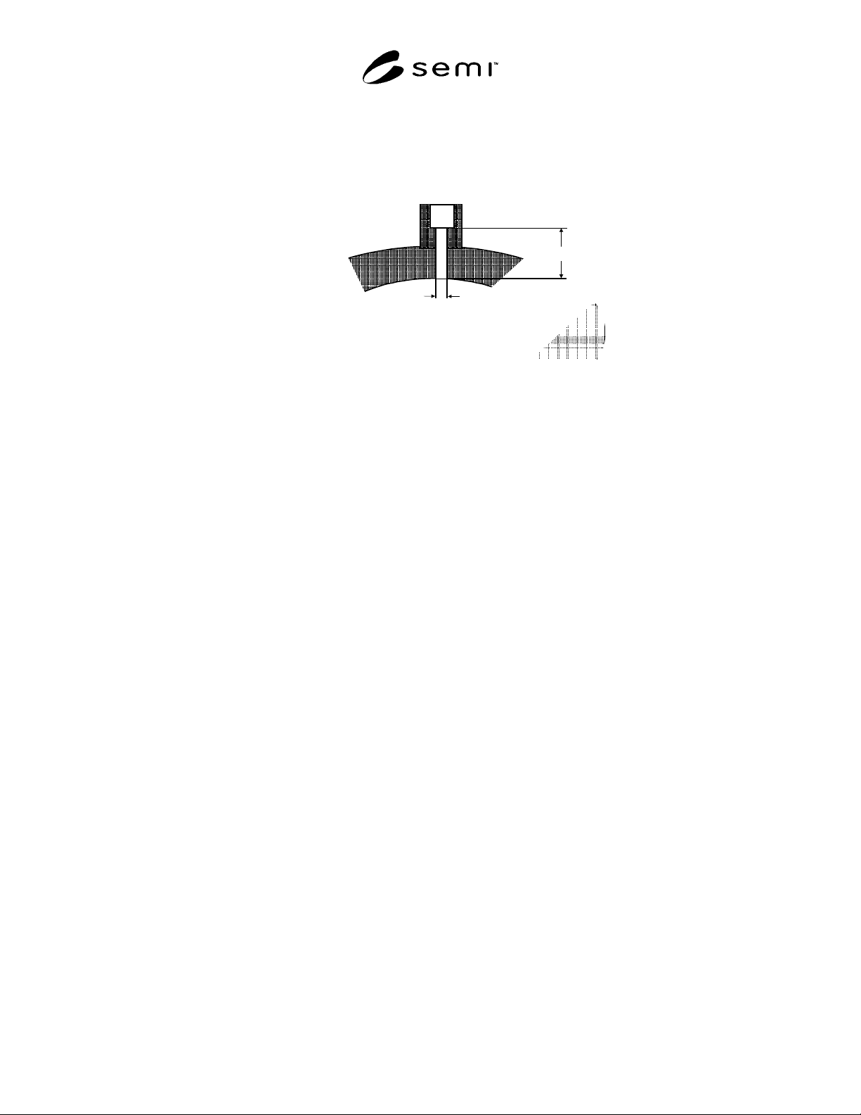
Size of Pipe “A” Not Exceeding “A” Not Less than
Less than 50 mm (2 in.) 6 mm (1/4 in.) 3 mm (1/8 in.)
50 mm to 75 mm (2–3 in.) 9 mm (3/8 in.) 3 mm (1/8 in.)
100 mm to 200 mm (4–8 in.) 13 mm (1/2 in.) 3 mm (1/8 in.)
250 mm and greater ( 10 in. and greater) 19 mm (3/4 in.) 3 mm (1/8 in.)
NOTE 1: Edge of hole must be clean and sharp or slightly rounded, free from burrs, wire edges or other irregularities. In no case
shall fitting protrude inside pipe.
NOTE 2: Any suitable method of making the physical connection is acceptable if above recommendations are adhered to.
See ASME Performance Test Code PTC 19.5-1972, “Applications. Part II of Fluid Meters, Interim Supplement on
Instruments and Apparatus.
Figure 3
Recommended Pressure Connection