semi合集-English.pdf - 第5462页
SEMI PR9-0705 © SEMI 2005 6 7.7.1.2. 10 Esters — dimethylphthal ate 7.7.1.2. 11 Chlorina ted Solvents — methyl ene chloride, perchloroe thylene, carbon tet rachloride 7.7.1.2. 12 Freon ® — Freon — TF, Freon — TMC, Freon …

SEMI PR9-0705 © SEMI 2005 5
7.5.6 Overall Dimensions
7.6 Possible root causes for chemical/materials incompatibility are partially listed below.
7.6.1 Cleanliness of fluid system
7.6.2 Outgassing of materials from solid surfaces into process fluid
7.6.3 Process fluid purity (trace chemical impurities)
7.6.4 Process fluid cleanliness (particulate)
7.6.5 Permeability of chemicals in solid materials
7.6.6 Infectious biomaterial
7.6.7 Corrosion-Erosion
7.7 Classification of materials and fluids
7.7.1 Fluids
7.7.1.1 Classification of Gases
5
(with examples)
7.7.1.1.1 Inerts — argon, helium, krypton, neon, radon, xenon
7.7.1.1.2 Hydrogen — deuterium, hydrogen, tritium
7.7.1.1.3 Hydrocarbons — acetone, acetylene, hexane, propane
7.7.1.1.4 Halogenated Hydrocarbons — carbon tetraflouride, octafluorocyclobutane
7.7.1.1.5 Hydrides — silane, germane, phosphine, arsine
7.7.1.1.6 Halogens, other than Fluorine — chlorine, iodine
7.7.1.1.7 Halides, other than Fluorides — hydrogen chloride, hydrogen bromide, hydrogen iodine
7.7.1.1.8 Fluorine and Fluorides — F
2
, XeF
2
, NF
3
, BF
3
,WF
6
7.7.1.1.9 Organo — Metallic and Siloxanes
7.7.1.1.10 Oxygen, Oxides and Sulfides
7.7.1.1.11 Nitrogen and Nitrogen Compounds
7.7.1.1.12 Acids — hydroflouric acid, nitric acid, sulfuric acid
7.7.1.1.13 Nano structures and compounds
7.7.1.2 Liquids
6
7.7.1.2.1 Water — de-ionized, distilled
7.7.1.2.2 Inorganic Acids — hydrochloric acid, hydrofluoric acid, nitric acid
7.7.1.2.3 Bases — sodium hydroxide, potassium hydroxide, ammonium hydroxide
7.7.1.2.4 Organic acids — glacial acetic, trichloroacetic
7.7.1.2.5 Hydrocarbon solutions — toluene, iso-octane
7.7.1.2.6 Alcohols — ethyl, isopropanol, methyl
7.7.1.2.7 Amines — aniline, ethylenediamine
7.7.1.2.8 Ethers — tetrahydrofuran
7.7.1.2.9 Ketones/Aldehydes — acetone, benzaldehyde, methyl ethyl ketone
5 SEMI F79-0703 Guideline for Gas Compatibility with Silicon used in Gas Distribution Components
6 http://www.entegrisfluidhandling.com
SEMI PR9-0705 © SEMI 2005 6
7.7.1.2.10 Esters — dimethylphthalate
7.7.1.2.11 Chlorinated Solvents — methylene chloride, perchloroethylene, carbon tetrachloride
7.7.1.2.12 Freon
®
— Freon — TF, Freon — TMC, Freon TMS
7.7.1.3 Classification of Materials; Common materials are considered
7
as follows (including in the nanometer size
regime):
7.7.1.3.1 Silicon — Element 14 (and all isotopes), single crystal, doped, polycrystalline, amorphous
7.7.1.3.2 Polymers — PCTFE, PTFE, Polyimide, Chemraz
®
, Kalrez, Viton
®
7.7.1.3.3 Glassy Materials — Silicon dioxide, Pyrex
®
, silicon nitride
7.7.1.3.4 Metals — Aluminum, stainless steel 316L, Hastelloy
®
c-22, Elgiloy
®
, Nickel 200
7.7.1.3.5 Ceramics — Alumina, Macor
®
7.7.1.3.6 Plastics — Polyethylene, PVC
7.7.1.3.7 Graphitic — nanotubes, C60, graphite, pyrolytic graphite, diamond-like carbon
7.7.1.3.8 Suspended Nano structures and compounds
7.7.1.4 Biological Materials
7.7.1.4.1 tissue
7.7.1.4.2 Viruses
7.7.1.4.3 DNA
7.7.1.4.4 Proteins
7.7.1.4.5 Polypeptides
7.7.1.4.6 Cellular materials
7.8 Materials/Chemical Compatibility
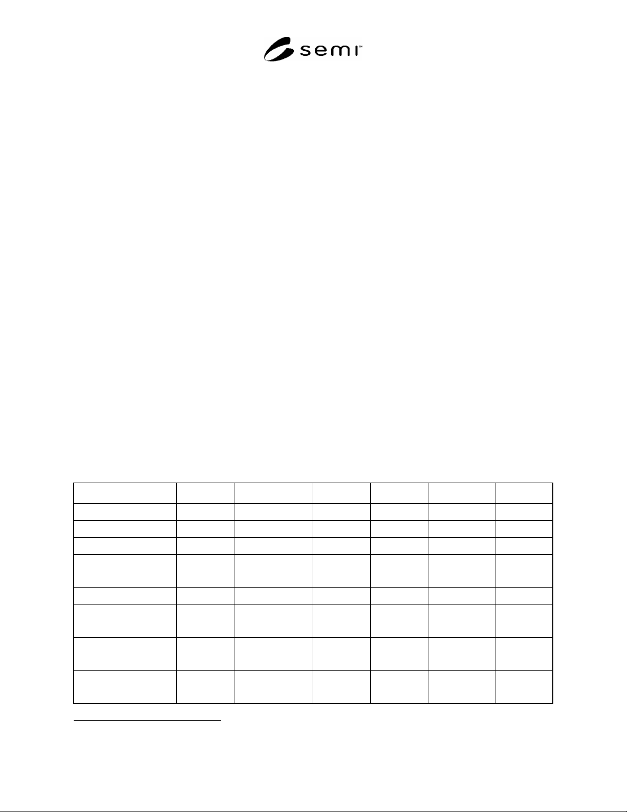
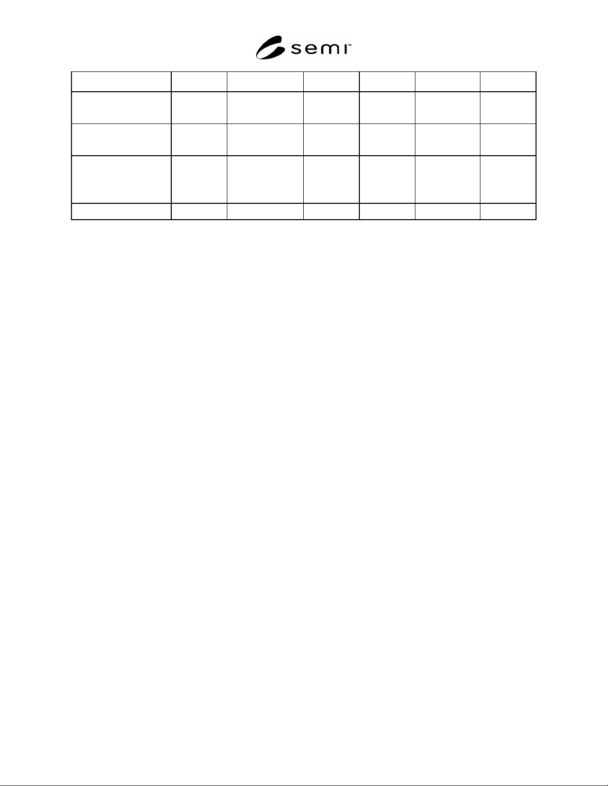
7.8.1 The compatibility chart below, is presented as a broad cross-section of materials and fluids that may be used
as a springboard for further development of fluidic devices and/or interfaces.
Silicon Polymers Glass Metals Ceramics Plastics
Inerts
A A A A A A
Hydrogen
5 7 7 7
Hydrocarbons
5 5,7 7 7
Halogenated
Hydrocarbons
5
Hydrides
5 7 7 7
Halogens, other than
Fluorine
5 7 7 7
Halides, other than
Fluorides
5 7 7 7
Fluorine and Fluorides
U/5 7 7 7
7 http://www.airproducts.com/specgases/safety/70008.htm
SEMI PR9-0705 © SEMI 2005 7
Silicon Polymers Glass Metals Ceramics Plastics
Organo-Metallic and
Siloxanes
5
Oxygen, Oxides and
Sulfides
5 7 7 7
Nitrogen and Nitrogen
Compounds
5 7 7 7
Acids
U 6 7 7
#1
A = Acceptable. This combination of fluid and material is acceptable or generally acceptable use when small effects of
permeation are inconsequential to use.
#2
U = Unacceptable in most applications where material and chemical interaction are significant.
#3
number = see footnote.
7.8.2 Example of How to Use This Chart and Guide
7.8.2.1 An engineering team is tasked to design a portable, matchbox-sized analytical system to detect, quantify,
and transmit data on abnormal airborne bio excursions.
8 Component Specific Guidelines
8.1 Purpose — To provide guidance on connection (methods) of discrete and integrated fluidic interconnects.”
8.2 Scope — These methods are limited to connections from microfluidic components to other microfluidic
components, and from microfluidic components to fluidic adapters.
8.3 Category — discrete and/or integrated components that provide interconnects on chip or between chips.
Examples of applications include: pressure sensor, flow sensor, temperature sensor, valves and pumps, as well as
adaptors. They can integrate with fluidic interconnect components.
8.4 Fabrication method — This section mainly discusses wafer-level interconnect fabrication methods.
8.4.1 Fusion bonding for Si wafers. Suitable for wafers that can tolerate high processing temperature
8.4.2 Anodic bonding for Si/Glass. Suitable for wafers that can tolerate high temperature and strong electrical field
8.4.3 Polymer bonding with intermediate layers such as SU-8, polyimide, PMMA, and BCB. Low temperature
bonding technique that is suitable for bioassays and post CMOS device integration with MEMS components. The
bonding chemical environment may be harmful to some biochemical chip functions and must be managed carefully.
8.4.4 Double side tape with pressurized press. Assembly method to make components, subsystems or system.
8.4.5 Thermocompression bonding. Use metal intermediate layer. Suitable for fluids containing organic solvents.
8.5 Adapters
8.5.1 End fittings (VCR
®
, Swagelok). Refer to manufacturer’s instructions. They are typically comprised of a nut
and a ferrule—have the important function of providing the physical connection of tubing throughout a chip and
between chips.
8.6 Testing and Validation
8.6.1 The following are guidelines for validation and testing of the integrity of the components
8.6.2 Standard pull test. This evaluates the bonding strength, but not sealing quality. Refer to tool manufacturer’s
manual from suppliers such as Instron, Zwick and MTS.
8.6.3 Pressurized test. Test the maximum pressure the component can survive according to the specifications of the
designed device.