semi合集-English.pdf - 第4243页
SEMI F77-0703 © SEMI 2003 2 4.2 ASTM 1 Standar ds ASTM G3 — Standard Practice for Conventions Applicable to Electroch em ical Measurements in Corrosion Test ing ASTM G15 — Standa rd Terminol ogy Relati ng to Corrosion an…

SEMI F77-0703 © SEMI 2003 1
SEMI F77-0703
TEST METHOD FOR ELECTROCHEMICAL CRITICAL PITTING
TEMPERATURE TESTING OF ALLOY SURFACES USED IN
CORROSIVE GAS SYSTEMS
This test method was technically approved by the Global Gases Committee and is the direct responsibility of
the North American Gases Committee. Current edition approved by the North American Regional Standards
Committee on April 11, 2003. Initially available at www.semi.org June 2003; to be published July 2003.
1 Purpose
1.1 The purpose of this test method is to determine the
relative resistance to pitting corrosion of the wetted
surfaces of components intended for use in corrosive
gas distribution systems for semiconductor
manufacturing. This test method is intended to
differentiate between alloy compositions and processes
intended to enhance the corrosion performance of the
wetted surfaces.
2 Scope
2.1 This test method describes a procedure, based on
the electrochemical critical pitting temperature (CPT),
which is used to rank the pitting corrosion resistance of
wetted surfaces of tubing or test coupons of
representative finished surfaces intended for use in
corrosive gas systems. Pitting corrosion is believed to
be a major corrosion failure mode in semiconductor gas
delivery systems, particularly in components and tubing
welded and exposed to corrosive gases.
2.2 This test method is an adaptation of ASTM G150.
The adaptation describes a method for performing the
test method on coupons or wetted-surface sections cut
from gas supply system components such as tubing. It
is an aqueous immersion method.
2.3 The test method is reproducible and provides a
metric (critical pitting temperature) in addition to a
qualitative (visual) evaluation of corrosion resistance.
2.4 This test method applies to materials as specified in
SEMI Standards referenced in Section 4.1, and to welds
of these materials.
2.5 This test method may also be used for other
corrosion resistant alloys and their welds not referenced
in Section 4.1.
NOTICE: This standard does not purport to address
safety issues, if any, associated with its use. It is the
responsibility of the users of this standard to establish
appropriate safety health practices and determine the
applicability of regulatory or other limitations prior to
use.
3 Limitations
3.1 Only analysts familiar with the instrumentation and
technique should use this test method.
3.2 The test conditions of this test method do not
simulate actual service in a corrosive gas supply
system. Thus the test results may not correlate to
relative corrosion resistance in a specific corrosive gas
or corrosive gas supply system.
3.3 The Critical Pitting Temperature (CPT) is valid
only in a range of 10° C to 95° C. A CPT result greater
than 95° C is not considered to be valid since it is
approaching the boiling point of the solution. A critical
pitting temperature (CPT) below 10° C shall only be
reported as < 10° C and may be an indication of crevice
corrosion.
3.4 Since alloy composition and surface parameters
can affect the results of the test (e.g., surface finish), all
variables other than the one being tested must be fixed
during the test in order to obtain reproducible and
comparable results.
3.5 The bias for this test has not yet been determined.
4 Referenced Standards
4.1 SEMI Standards
SEMI F2 — Specification for 316L Stainless Steel
Tubing for General Purpose Semiconductor
Manufacturing Applications
SEMI F17 — Specification for High Purity Quality
Electropolished 316L Stainless Steel Tubing,
Component Tube Stubs, and Fittings made from Tubing
SEMI F19 — Specification for the Finish of the Wetted
Surfaces of Electropolished 316L Stainless Steel
Components
SEMI F20 — Specification for 316L Stainless Steel
Bar, Extruded Shapes, Plate, and Investment Castings
for Components Used in High Purity Semiconductor
Manufacturing Applications
SEMI F77-0703 © SEMI 2003 2
4.2 ASTM
1
Standards
ASTM G3 — Standard Practice for Conventions
Applicable to Electrochemical Measurements in
Corrosion Testing
ASTM G15 — Standard Terminology Relating to
Corrosion and Corrosion Testing
ASTM G150 — Test Method for Electrochemical
Critical Pitting Temperature Testing of Stainless Steels
NOTICE: Unless otherwise indicated, all documents
cited shall be the latest published versions.
5 Terminology
NOTE 1: Unless otherwise stated, the sign conventions used
in this test method are in agreement with ASTM G3, and the
terminology relating to corrosion and corrosion testing is as
defined in G15.
5.1 Definitions
5.1.1 CPT-Critical Pitting Temperature — the lowest
temperature at which stable propagating pitting occurs
on the test surface under the specified test conditions, as
indicated by a rapid increase beyond a specified limit of
the measured anodic current density of the test surface.
5.1.2 passive potential range — the potential range
over which the current density is independent of
potential. The current is a very low value due to
formation of an oxide layer.
5.1.3 pitting — corrosion of a metal surface, confined
to a point or small area, that takes the form of cavities.
5.1.4 pitting potential range — the range of measured
potentials where pitting is initiated. This potential
range only exists above the minimum CPT.
5.1.5 potential dependent CPT — the CPT determined
at a potential within the pitting potential range of the
tested surface.
5.1.6 potential independent CPT — the CPT
determined at a potential above the pitting potential
range, but below the transpassive potential range.
5.1.7 temperature ramp — the rate (° C/min) at which
the test temperature is increased during the test.
5.1.8 transpassive potential — the potential above the
passive potential range, in which the current density
increases rapidly as the potential increases.
5.1.9 wetted surface — surfaces of a component in
contact with the contained fluids.
1 Available from American Society for Testing and Materials, 100
Barr Harbor Drive, PO Box C700, West Conshohocken, PA 19428-
2959. Fax: 1-610-832-9555. Website: http://www.astm.org.
6 Summary of Method
6.1 The test method measures the critical pitting
temperature (CPT) by using a potentiostatic technique
and a temperature scan. Specific types of specimen
holders are used to minimize crevice corrosion, which
is another type of corrosion mechanism that can
complicate the CPT result. The test is performed in an
aqueous electrolyte solution, such as 1 M NaCl. After
polarizing the specimen to a potential above the pitting
potential, the temperature scan begins at 0°C. The
solution is heated at a constant rate of 1°C/minute while
the current is measured by means of a
potentiostat/galvanostat instrument. The CPT, as
defined in Section 5.1.1, is the temperature at which the
current density increases above 100 µ A/cm
2
for 60
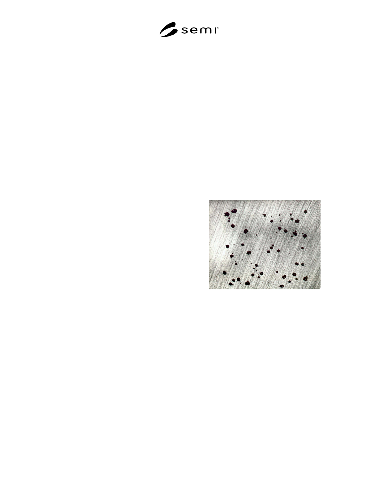
seconds. Pitting is normally confirmed by visual or
microscopic observation of the specimen after testing as
shown in Figure 1. Refer to Appendix X1 in ASTM
G150 for a description of the relationship between the
pitting potential and the critical pitting temperature.
Figure 1
Examples of Pitting on Type 316 Stainless Steel
After a Pitting Potential Test Performed at 25°C in 1
M NaCl (11 × Magnification)
(Ref 17.1)
SEMI F77-0703 © SEMI 2003 3
7 Possible Interferences
7.1 Specimens must be examined after testing to
confirm pitting. A possible interference is failure by
crevice corrosion in which case the test is invalid.
Crevice corrosion can occur at the seal of the specimen
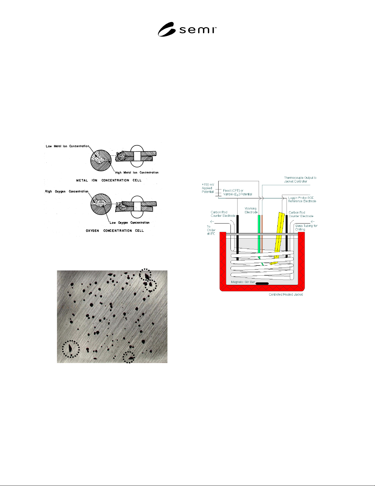
holder. Figure 2 shows the mechanism by which
crevice corrosion occurs, and Figure 3 gives an
example of the typical morphology of crevice corrosion
from a pitting potential test performed on type 316
stainless steel using masked edges. It should also be
noted that the critical crevice temperature (CCT) for
AISI 316L is less than 10°C.
Figure 2
Mechanism for Crevice Corrosion
(See Section 17.2.)
Figure 3
Examples of Crevice Corrosion (Dashed Circles) on
Type 316 Stainless Steel After a Pitting Potential
Test in 1 M NaCl at 35°C. 11 × Magnification (See
Section 17.1.)
8 Apparatus
8.1 In general, refer to ASTM G150 for a detailed
description of the apparatus and accessories necessary
to carry out the CPT evaluation. Specifically, Sections
6.1 to 6.9 of ASTM G150 describe the potentiostat, the
potential measuring instrument, the current measuring
instrument, the temperature controller, and the
temperature measurement instrumentation.
8.2 Flat Specimens — The test cell for flat specimens
(consisting of two options, G5-type cell and a flushed-
port cell), are given in Appendices X2 and X3 of
ASTM G150 with a detailed description of each.
8.3 Tubular Specimens — The test cell can be modified
for testing tubular specimens. The modified test cell
consists of a 2-L glass beaker cut to 4.5 in. high and
capped with a polyethylene cover. A three-electrode
set up is used consisting of the test specimen, an SCE
reference electrode inserted in a Luggin probe, and two
graphite rods as counter electrodes. See Figure 4 for the
modified test cell set-up.
Figure 4
Modified Test Cell for CPT Testing of Tubular
Specimens; Tubing Specimen is the Working
Electrode
9 Test Specimens
9.1 Flat Specimens — In general, refer to ASTM G150
for a detailed description of the flat specimen.
9.2 Tubing Specimens — Tubing specimens consist of
2.0-in. lengths of tubing. The tubing should be faced,
and the cut ends should be masked with a non-reactive
lacquer.
9.3 All specimens should be masked to isolate the test
to the surface of interest only. This can be
accomplished by masking with a non-reactive lacquer,
which can be baked to ensure optimum adhesion.