semi合集-English.pdf - 第3210页
SEMI E127-0705 © SEMI 2003, 2005 11 table retention conditions (¶11 .3.4). 9.2.2.1 In addition, each client may request these settings at any time and receive only their own settings in response. 9.2.3 The first messag…

SEMI E127-0705 © SEMI 2003, 2005 10
7.6 Service Requirements
7.6.1 This document does not redefine services defined in other SEMI standards. However, for emphasis, those that
are beyond the requirements of fundamental compliance to other standards are included in the lists of services as
applicable.
8 Overview
8.1 Background
8.1.1 Both modern manufacturing processes and modern manufacturing equipment are increasingly complex. A
single installation of equipment may have hundreds of sensors and actuators. In order to manage this complexity,
better methods of referencing the internal components of equipment are needed. Use of the object paradigm
provides a means for the equipment to describe its internal composition to the factory in a natural way.
8.1.2 Definition of standardized objects allows the factory to be specific about its requirements and its need for
information.
8.1.3 The measurement module is not concerned about the role of its client. Depending on the architectural layout,
it might be communicating with the controller of the integrated equipment, the controller of the equipment’s front-
end carrier handling module or the factory host.
8.1.4 The IMM is one module of many that receive instructions about a specific substrate. The substrate may be
given to the IMM at any point in a sequence of individual process steps. While it typically may be the first or the
last in the sequence, or both, it may also appear at any point in the middle.
8.1.5 The IMM is given a substrate, a recipe, and a process job. It may or may not have an alignment station, and it
may or may not be able to contain more than one substrate at a time. For example, it might be able to align one
substrate while it is executing a process job on a previous substrate. Also, the IMM may or may not have an
integrated data analysis subsystem. Modules with data analysis capability may require additional processing time to
complete the analysis. Finally, the substrate is unloaded and the results of the measurement are sent on the data port.
9 Communication Ports and Clients
9.1 Ports
9.1.1 The IMM shall provide two or more communication ports, one of which to be used for control as well as
information and is called the primary port. Other ports are called secondary ports and are mainly used for sending
and receiving information to applications that may be either on- or off-tool, such as remote process control and/or
fault detection, archiving substrate data tables, uploading and downloading recipes, etc.
9.1.2 Control in this case signifies the request for services that can change the hardware state of the integrated
metrology module, including substrate exchange, process jobs, clock services, and maintenance-related activities. In
general, the controller of the process tool, or one of its major components, will require the use of the primary port
for control, although there may be special circumstances where this is not true.
9.1.3 The IMM shall support one or more additional communication ports to be used mainly for sending and/or
receiving information, such as event reports, alarm-related messages, recipes, and data tables. It is recommended
that at least one of the additional ports be physically separate to allow a connection to a different network.
9.1.4 The requirement to support a second or multiple ports is a requirement on the IMM side of the communication
only. The decision to utilize these ports, and the manner in which they are utilized, is left to the application of the
integrated metrology tool and the factory.
9.2 Clients
9.2.1 There are two types of clients, the Control Client and the Data Client.
9.2.2 All clients are able to configure the following independently of other clients:
event reports,
alarm reports, and

SEMI E127-0705 © SEMI 2003, 2005 11
table retention conditions (¶11.3.4).
9.2.2.1 In addition, each client may request these settings at any time and receive only their own settings in
response.
9.2.3 The first message that the IMM receives from a potential client must be the ClientConnect Service request.
This message is used to establish a client as either the Control Client or a Data Client. All other service requests
from an unestablished client shall be rejected. At any point in time, there shall be no more than one Control Client.
9.2.4 The Control Client
9.2.4.1 The Control Client is a client who intends to request services that may change the physical state of the
hardware of the IMM. Such services include those used for substrate exchange, process jobs, and any maintenance
activities. In general, this will be the controller of the integrated metrology tool or one of its major components. It
is up to the implementer whether clients connecting through a port other than the primary port can establish
themselves as the Control Client.
9.2.4.2 The Control Client shall be able to use all IMM capabilities specified in this standard. Only the Control
Client shall be permitted to use the IMM Clock Services and Process Job services, or to issue service requests that
change the state of the hardware.
9.2.4.3 Once a Control Client is established through use of the ClientConnect service, it remains established as the
Control Client until it disconnects by sending the ClientDisconnect Service request.
9.2.4.3.1 During the time that a Control Client is established, any requests to be a Control Client shall be rejected,
and any requests for services that can change the state of the hardware from other clients shall be rejected.
9.2.4.3.2 Once the Control Client has disconnected, then another client may request to establish itself as the Control
Client.
9.2.4.4 The Control Client shall be able to use all IMM capabilities specified in this standard. Only the Control
Client shall be permitted to use the IMM Clock Services and Process Job services, or to issue service requests that
change the state of the hardware.
9.2.5 Data Clients
9.2.5.1 The Data Client is a client who intends to request services for information only and not for any services that
may change the physical state of the hardware of the IMM. Each Data Client may request information at any time.
9.2.5.2 The use of the Data Client is optional for the end-user.
9.3 Bandwidth and Performance
9.3.1 The IMM is responsible for managing its own bandwidth and performance. This standard allows for delays in
message transmission in a multi-client environment in order to protect the integrity of the IMM measurement and
data conversion abilities.
10 Integrated Measurement Module Object Model
10.1 Description
10.1.1 The Integrated Measurement Module (IMM) conforms to the architectural specification of the
EquipmentModule object as defined in SEMI E120 (CEM).
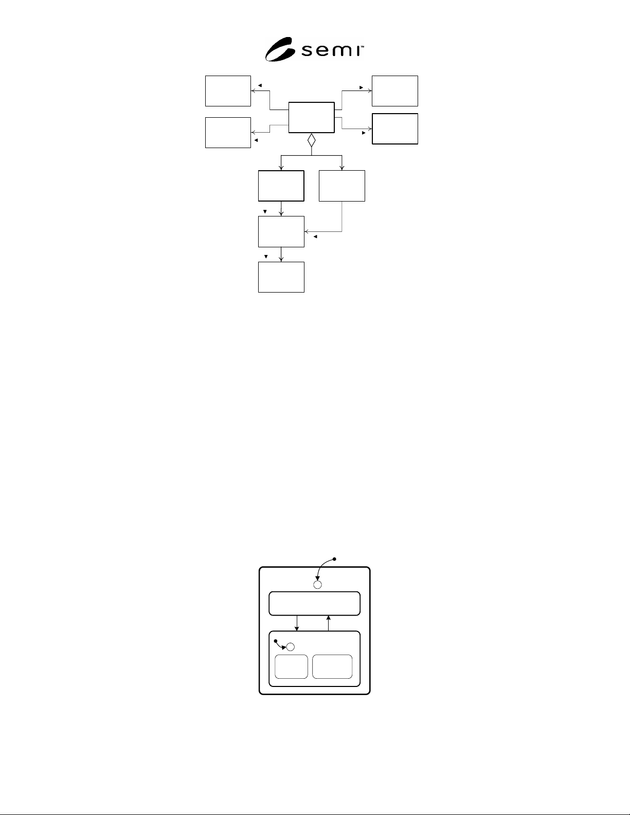
10.1.2 Figure 1 shows an object model for the Integrated Measurement Module and its significant components.
SEMI E127-0705 © SEMI 2003, 2005 12
Integrated
Measurement
Module
Subsystem
1...*
0...*
Substrate
Transfer Path
0...*
Clock
0...*
IMM Data
Table
Substrate
Location
Substrate
0...*
occupied by
0...*
Process
Job
Recipe
manages
uses
contains
0...*
0...*
1
provides
manages
provides
Figure 1
IMM Object Model
10.1.3 The IMM has exactly one internal clock. It must have one or more measurement subsystems capable of
holding one or more substrates in a substrate location. It may have additional components, such as OCR
subsystems. Pattern recognition and analysis subsystem typically do not hold any material. The Clock shall be
provided as an OBEM-compliant clock object. Subsystems shown in Figure 1 are not required to be visible as
objects externally.
11 The Integrated Measurement Module Object
11.1 Relationship of IMM Object And Physical Module
11.1.1 The IMM object represents the IMM module and all of its internal components to its client. It is responsible
for ensuring proper behavior in all cases. In this document, the IMM object is considered synonymous with the
IMM module. The IMM provides all services to the client other than those specifically directed to the STPO,
including those specified by other SEMI standards.
11.2 IMM Service State Model
11.2.1 The IMM is either in a state where it can be used for normal measuring purposes or it is not. This is
reflected in the Service State Model as shown in Figure 2.
SERVICE
C
1
IN SERVICE
3
EXTERNAL
SELECT
INTERNAL
SELECT
2
C
4
NOT IN
SERVICE
Figure 2
IMM Service State Model