semi合集-English.pdf - 第6954页
SEMI S8-0705 © SEMI 1995, 2005 51 Section 7: Maintainability and Serviceability Section Indicator Figure 7.3.7 Clearance provided for one arm to elbow access, diameter, or s quare area (does not ensure visual a ccess). M…
SEMI S8-0705 © SEMI 1995, 2005 50
Section 7: Maintainability and Serviceability
Section Indicator Figure
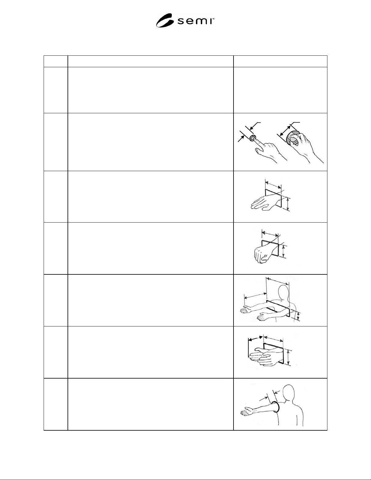
7.3
Hand/arm clearance. (Note: where appropriate to do so, adjustments have
been made for cleanroom gloves.)
NOTE A: Access openings should have smooth edges.
NOTE B: If hinged doors are used, they should not interfere with
access.
7.3.1 Clearance provided for finger access round (diameter) or square.
One finger: minimum 32 mm (1.25 in.)
2, 3 or 4 finger twist of small knob: minimum object diameter + 58 mm
(2.3 in.)
Single
Finger
2 – 4
Fingers
7.3.2
Clearance provided for flat hand wrist access.
Height, palm thickness: minimum 89 mm (3.5 in.)
Width, palm width: minimum 114 mm (4.5 in.)
Width
Height
7.3.3
Clearance provided for fist to wrist access.
Height (fist thickness): minimum height 89 mm (3.5 in.)
Width (fist width): minimum width 127 mm (5.0 in.)
Width
Height
7.3.4
Clearance provided for two hands arm to shoulders access (does not
ensure visual access)
Reach maximum 610 mm (24.0 in.)
Width: minimum 483 mm (19.0 in)
Height: minimum 114 mm (4.5 in.)
Width
Height
Reach
7.3.5
Clearance provided for two hands, hand to wrist access (does not ensure
visual access)
Reach: maximum 203 mm (8.0 in.)
Width: minimum 191 mm (7.5 in)
Height: minimum 114 mm (4.5 in.)
Width
Height
Reach
7.3.6
Clearance provided for one arm to shoulder access (does not ensure
visual access)
Minimum clearance 132 mm (5.2 in.)
Clearance
SEMI S8-0705 © SEMI 1995, 2005 51
Section 7: Maintainability and Serviceability
Section Indicator Figure
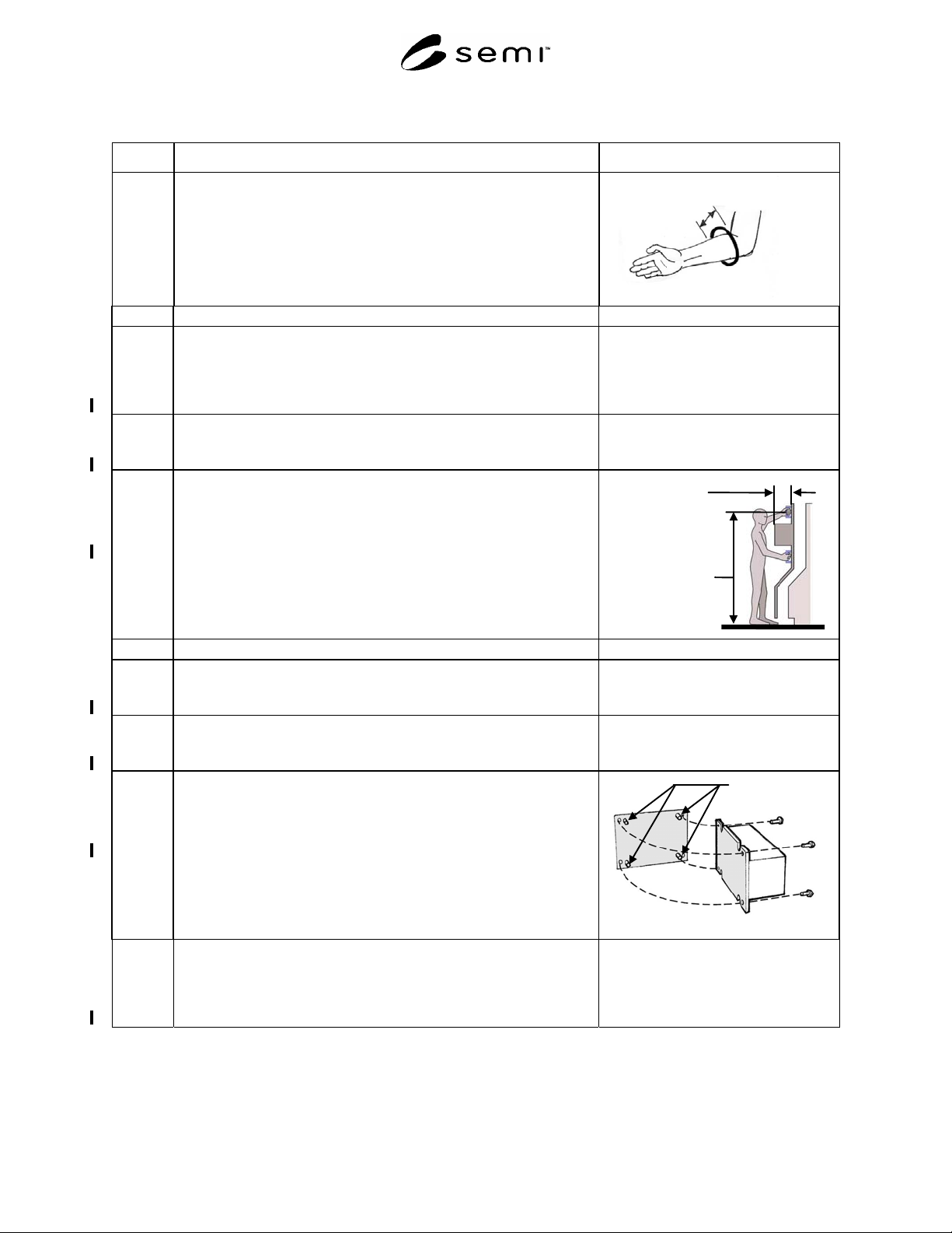
7.3.7
Clearance provided for one arm to elbow access, diameter, or square area
(does not ensure visual access).
Minimum 119 mm (4.7 in.)
Clearance
7.4 Maintenance and Service Access
7.4.1 Enclosures or covers must, unless fully removable, be self-supporting, in
the open position, and not require manual support during maintenance.
Exceptions may be allowed for self-closing doors for fire safety or
compliance reasons.
Acceptance criterion: supports present
7.4.2 Access covers should be equipped with full-handed grasp areas or other
means for opening them.
Acceptance criterion: handles present, refer to Section 6 for design criteria
7.4.3 Height of access cover handle over the entire range of motion required for
operation or maintenance.
There should be no greater than a 254 mm (10 in.) deep obstruction in
front of the handle.
Acceptance criterion: maximum 1700 mm (67 in.)
Obstruction in
front of handle
Maximum 254
mm
(10 in.)
Handle height
over entire
range of motion
Maximum 1700
mm
(67 in.)
7.5 Replaceable Components
7.5.1 Serviceable components are replaceable as modular packages, and are
configured for rapid removal and replacement.
Acceptance criterion: serviceable components configured as described
7.5.2 Serviceable components should not be stacked directly on one another
(i.e., a lower layer should not support an upper layer).
Acceptance criterion: serviceable components independently accessible
7.5.3 Heavy components (objects which have a lifting index of 0.5 or greater,
see SESC, Section 1.0) or bulky components (greater than 36 inches in
length) requiring frequent removal/installation should include
guide/locating aids to assist in positioning.
Acceptance criterion: guide/locating pins present
Locating pins
Example of locating pins
7.5.4 Cables, connectors, plugs, and receptacles should be labeled, keyed, color
coded, or otherwise configured to make connection easier and prevent
cross connection. This feature is assessed only if a SEMI S2 assessment is
not being conducted.
Acceptance criterion: identification present, keyed where needed
SEMI S8-0705 © SEMI 1995, 2005 52
Section 7: Maintainability and Serviceability
Section Indicator Figure
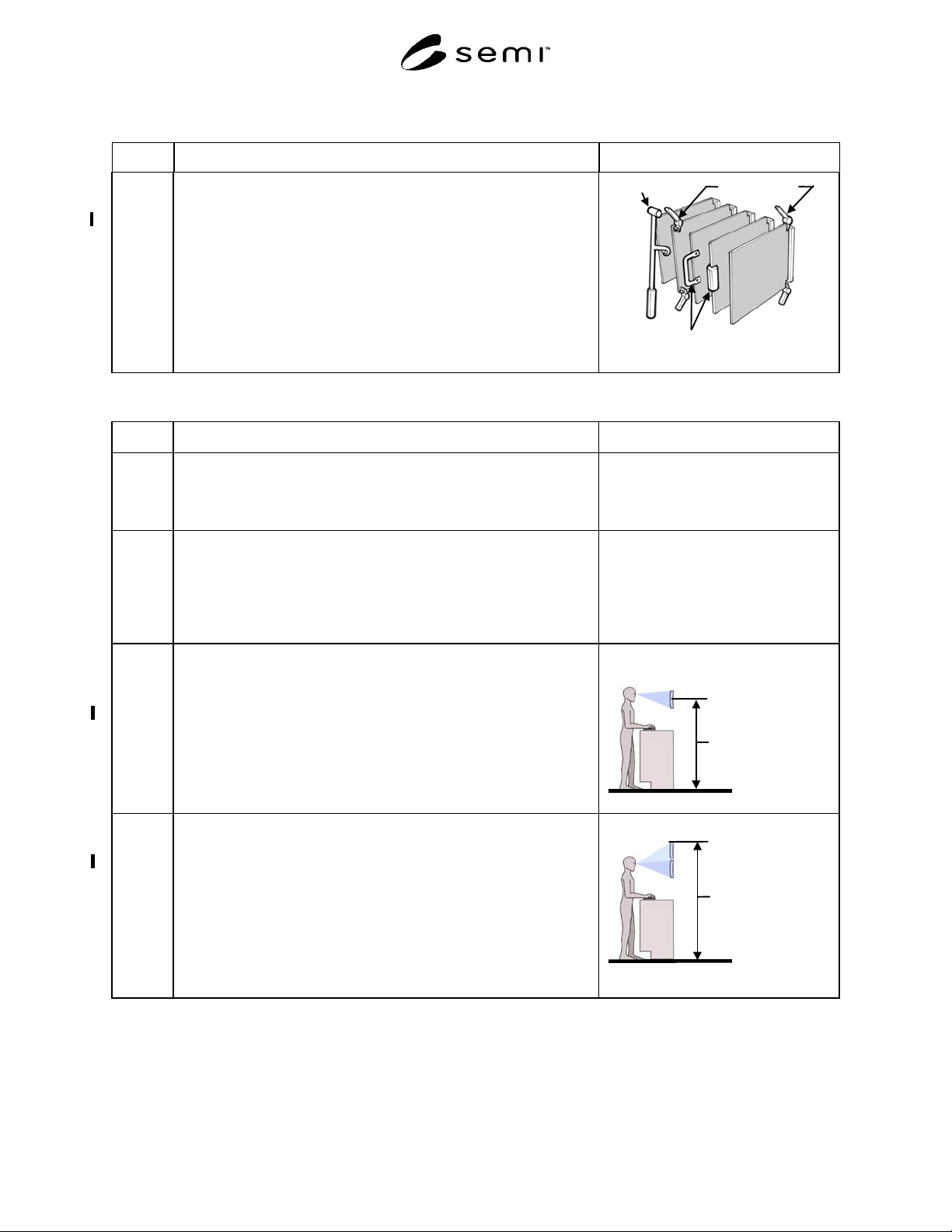
7.5.5 Circuit boards mounted in a card cage configuration should have gripping
or ejecting aids for mounting and removal.
Acceptance criterion: finger access, gripping, or ejecting aids available
Hand tool
E
j
ect levers
Handgrips
Circuit board removal device examples
Section 8: Display Location
Section Indicator Figure
8.0 Display Location
NOTE: Angle-adjustable displays allow the user optimize the
viewing angle to control glare and maximize comfort.
8.1 Location for operator primary interface, standing station.
NOTE: A standing station is one where the operator can assume a
standing posture or use a tall stool or chair which places the
operator at approximately the same height as a standing
posture.
8.1.1 Height of video display terminal (single monitor). Does not include
touchscreens, measured from floor to center of screen.
Acceptance criteria: maximum 1470 mm (58 in.)
minimum 1320 mm (52 in.)
NOTE: The display user should be able to view a display while
maintaining a near-neutral posture.
Single monitor
Maximum 1470
mm
(58 in.)
Minimum 1320
mm
(52 in.)
8.1.2 Height of video display terminal (stacked monitors). Does not include
touchscreens, measured from floor to top line of the top monitor.
Acceptance criterion: maximum 1680 mm (66 in.)
The primary monitor in a stacked configuration is the bottom monitor.
Top stacked
monitor
Maximum 1680 mm
(66 in.)