semi合集-English.pdf - 第1357页
SEMI E30-1103 © SEMI 1992, 2003 31 4.3 Alarm Management — The alarm m anagement capability provid es for host notification an d managem ent of alarm conditions occurring on the equipment. 4.3.1 Purpose — Historically, a …

SEMI E30-1103 © SEMI 1992, 2003
30
4.2.5.5 Scenario
Request Equipment Status Report:
COMMENT HOST EQUIPMENT COMMENT
Host requests report of selected
status variable values S1,F3-->
<--S1,F4 Equipment responds with the
requested status variable
data.
Request Equipment Status Variable Name list:
COMMENT HOST EQUIPMENT COMMENT
Host requests equipment to identify
selected status variables. S1,F11-->
<--S1,F12 Equipment responds with the
requested status variable
descriptions.
4.2.6 On-line Identification
4.2.6.1 Purpose — Implementation of SEMI E5 (a GEM Fundamental Requirement) requires the equipment to
accept the S1,F1 from the Host at any time while it is ONLINE and COMMUNICATING, and respond with S1,F2.
The On-line Identification capability describes the host-initiated scenario. The equipment-initiated scenario is used
for a different purpose and is defined in sections 3.3 and 4.12 describing the GEM “Control Model”.
4.2.6.2 Definitions
Equipment Model Type (MDLN) — ASCII string containing the equipment model. See SEMI E5 for a full definition
of this data item.
Equipment Software Revision Code (SOFTREV) — ASCII string containing the equipment software revision. See
SEMI E5 for a full definition of this data item.
4.2.6.3 Detailed Description — On-line Identification allows the host to verify the presence and identity of the
equipment.
4.2.6.4 Requirements — (Host-Initiated) An S1,F2 response from the equipment must provide MDLN and
SOFTREV information which reflects the hardware and software configuration of the equipment.
SOFTREV must uniquely identify different releases of equipment software. Any change in equipment software
must result in a corresponding change to SOFTREV.
The equipment-initiated S1,F1 is not required except as described in sections 3.3 and 4.12 describing the GEM
“Control Model”.
4.2.6.5 Scenario:
Host Initiated
COMMENT HOST EQUIPMENT COMMENT
Are you there? S1,F1-->
<--S1,F2 Equipment replies with MDLN and
SOFTREV.
SEMI E30-1103 © SEMI 1992, 2003
31
4.3 Alarm Management — The alarm management
capability provides for host notification and
management of alarm conditions occurring on the
equipment.
4.3.1 Purpose — Historically, a precise definition of
an equipment alarm has been absent. Consequently,
differing interpretations have resulted in inconsistent
implementations. This is addressed by providing a more
rigorous definition (see definition in Section 4.3.2
below) of an alarm.
In addition, it is often important for equipment to report
more extensive information to the host than has been
available in the S5,F1/F2 (Alarm Report Send/
Acknowledge) transaction. The data required in such
cases is very dependent on equipment type, host
information requirements, and alarm situation. This
issue is addressed by providing event reporting
methods that are tied to alarm state changes.
Lastly, the alarm management capability provides
mechanisms for:
— Reporting the time of an alarm state change,
— Uploading a list of alarm texts,
— Enabling and disabling the notification of specific
alarms, and
— Host query of alarms set and enabled status on the
equipment.
4.3.2 Definitions
Alarm — An alarm is related to any abnormal situation
on the equipment that may endanger people, equipment,
or material being processed. Such abnormal situations
are defined by the equipment manufacturer based on
physical safety limitations. Equipment activities
potentially impacted by the presence of an alarm shall
be inhibited.
Note that exceeding control limits associated with
process tolerance does not constitute an alarm nor do
normal equipment events such as the start or
completion of processing.
AlarmsEnabled — Status value consisting of a list of
the alarm ID’s currently enabled for reporting to the
host. See SEMI E5 for a full definition of this variable
data item.
AlarmsSet — Status value consisting of a list of the
alarm ID’s currently in the ALARM SET (or unsafe)
state. See SEMI E5 for a full definition of this variable
data item.
ALCD — Alarm code data item used in the S5,F1
(Alarm Report Send) and S5,F6 (List Alarm Data)
messages. This code is divided into two parts, the alarm
set/cleared bit and the 7 bit alarm category code. Only
the set/cleared bit is used—bit 8 = 1 means alarm set, =
0 means alarm cleared. The alarm category code is not
used. See SEMI E5 for a full definition of this data
item.
ALID — Alarm identifier. See SEMI E5 for a full
definition of this data item.
ALTX — Data item contained in the S5,F1 and S5,F6
messages containing a brief textual description of an
alarm. See SEMI E5 for a full definition of this data
item.
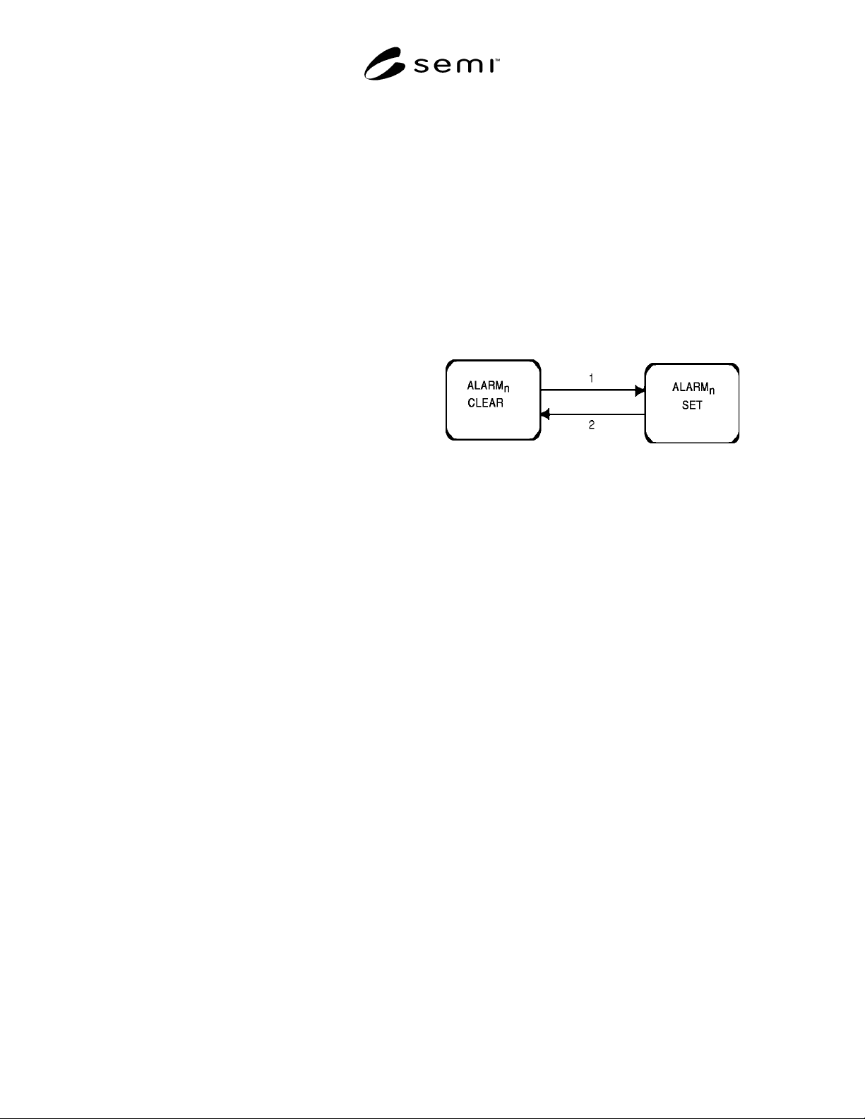
Figure 4.3
State Diagram for Alarm ALID
n
4.3.3 Detailed Description — Two alarm notification
mechanisms are defined to achieve the flexibility
necessary for the reporting required by host systems.
First, stream 5 alarm reporting enables a brief, yet
fixed, method for notification of alarm occurrences
using the S5,F1/F2 transaction. Second, to address the
host’s potential need for more extensive and flexible
data reporting, two collection events (“alarm set” and
“alarm cleared”) are defined for each possible alarm
condition on the equipment to allow the use of event
data collection mechanisms. In the latter case, reports
are sent by the equipment using the Event Report/
Acknowledge transaction (see Section 4.2 on event data
collection).
The alarm
n
detected and cleared events are derived
from the state model for an alarm (see Figure 4.3 and
Table 4.3.1). In this model each of n alarms can be in
one of two possible states, either ALARM CLEAR or
ALARM SET. The transition from the ALARM
CLEAR to the ALARM SET state is defined as the
collection event “Alarm
n
detected” (transition 1).
Conversely, the transition from ALARM SET to
ALARM CLEAR is defined as the collection event
“Alarm
n
cleared” (transition 2).
NOTE 8: The alarm capability is intended as an addition to
standard safety alarms (e.g., lights, horns). There is no intent
to replace direct operator notification of such problems, nor is
there the expectation that the host can prevent or directly
address such alarms.

SEMI E30-1103 © SEMI 1992, 2003
32
Table 4.3.1 Alarm State Transition Table
# Current Trigger New State Action Comment
1 ALARM
n
CLEAR
Alarm
n
is detected
on the equipment.
ALARM
n
SET
Initiate local actions (if any) to
ensure safety. Update
AlarmsSet and ALCD
n
values.
Generate and issue alarm
message if enabled.
Inhibited activities
require operator or
host intervention
prior to resuming.
2 ALARM
n
SET
Alarm
n
is no longer
detected on the
equipment.
ALARM
n
CLEAR Update AlarmsSet and ALCD
n
values. Generate and issue
alarm message if enabled.
Inhibited activities
require operator or
host intervention
prior to resuming.
The equipment manufacturer is responsible for identifying all alarms on their equipment by:
— Applying the above alarm definition,
— Consulting Application Note A.3 for examples of alarms for various equipment configurations,
— Noting that the presence of an alarm typically requires some action or intervention before resuming safe
operation of the equipment, and by
— Referring to Table 4.3.2 below which delineates the differences between events and alarms.
Table 4.3.2
EVENT ALARM
Any occurrence detectable by the equipment. Related to only those occurrences that are abnormal,
undesirable, AND endanger people, equipment, or physical
material being processed.
Certain events may trigger a state transition(s). Each alarm has an associated two-state state model: ALARM
SET (or unsafe) and ALARM CLEAR (or safe).
Equipment activities are not necessarily inhibited by the
occurrence of an event (unless it is associated with an alarm or
intentional inhibit).
The presence of an alarm inhibits equipment activities to
ensure safe operation until the alarm condition is cleared.
Certain events may occur in an expected sequence. Alarms may occur at any time.
4.3.3.1 Enable/Disable Alarms — Upon request from
the host, the equipment shall enable or disable reporting
of certain alarms. Enabling or disabling a given alarm
shall impact the communication of both the alarm set
and clear messages equally (i.e., turn them both on or
both off). This is not the case for enabling/disabling of
the associated collection events, where the alarm-set
and alarm-cleared events can be enabled and disabled
separately. The current enable/disable settings must be
stored in non-volatile memory. Changes to the
enable/disable settings must be reflected in the
AlarmsEnabled status value.
NOTE 9: The alarm itself is not being enabled or disabled,
but the reporting of the alarm through SECS-II messages is
being enabled or disabled.
4.3.3.2 Send Alarm Report — Upon detecting a change
in the status of a given alarm, an associated alarm state
model shall transition to the opposite state. Following
initiation of local actions necessary to ensure safety, the
equipment must update the AlarmsSet and associated
ALCD values and send an alarm message and/or an
event message to the host assuming one or both are
enabled. Alarm messages must be sent before the
corresponding event messages if both are enabled.
NOTE 10: The ALCD is divided into two parts, the alarm
set/cleared bit and the 7 bit alarm category code. Only the
set/cleared bit is used—bit 8 = 1 means alarm set, = 0 means
alarm cleared. The alarm category code is not used.
4.3.3.3 List Alarm Text — Upon request from the host,
the equipment sends values of alarm text associated