semi合集-English.pdf - 第4461页
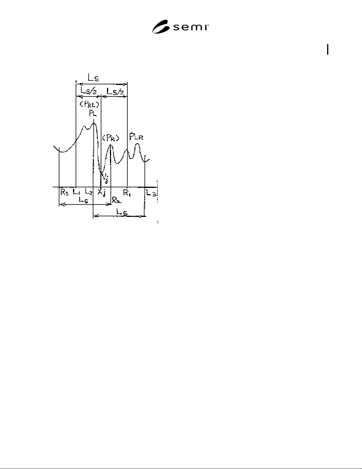
SEMI D15-1296 © SEMI 1996, 2003 6 4. Search th e highest point, P RL , in the window (R 3 − X j ). 5. W jR = | Z j − (P R + P RL ) /2 | Figure A1-2 Calculating Points of a Local Va lley A1-3.3.3 Calculate W jL and W j R …
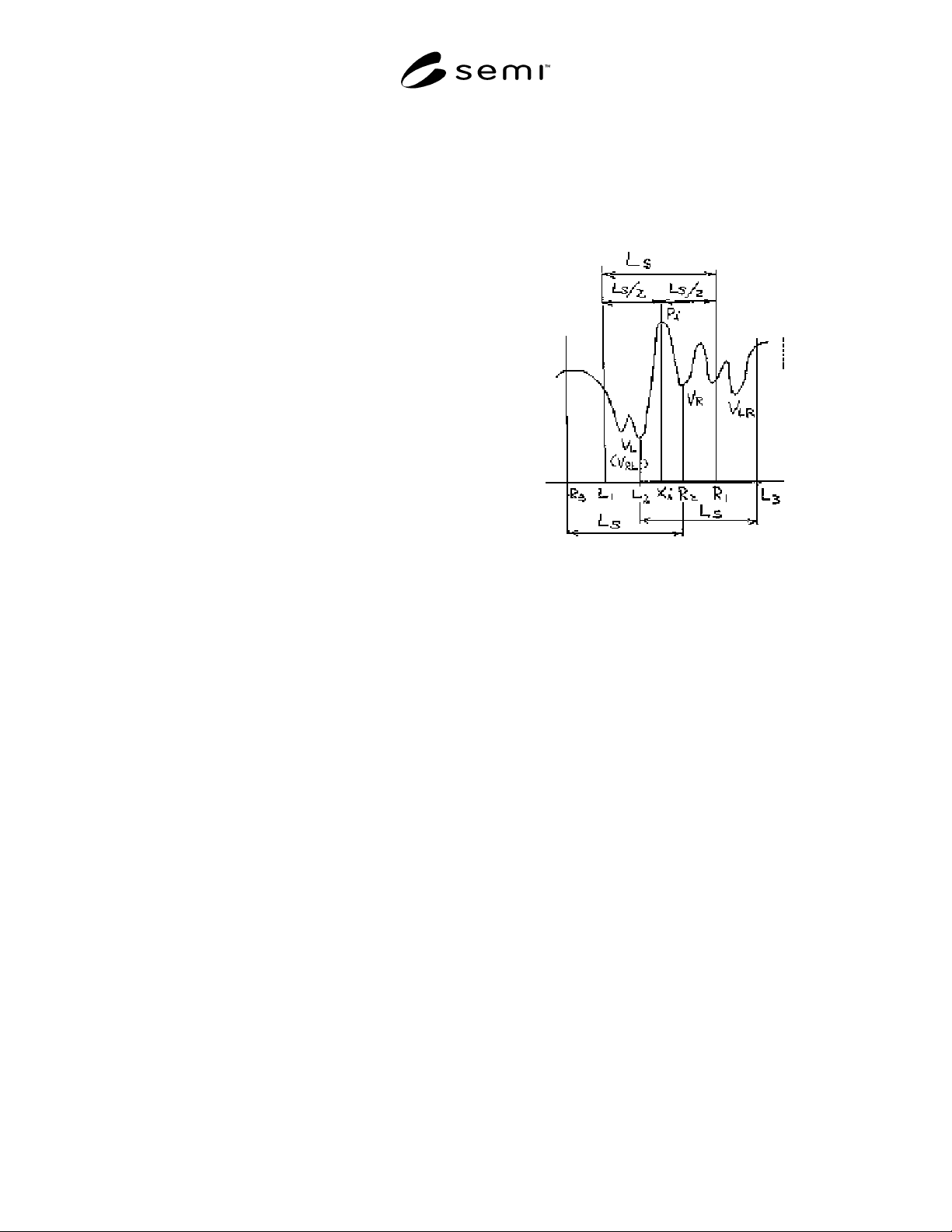
SEMI D15-1296 © SEMI 1996, 2003 5
APPENDIX 1
NOTICE: This appendix was approved as an official part of SEMI D15 by full letter ballot procedures.
A1-1 Purpose
A1-1.1 FPD waviness W
fpd
requires a large amount of
calculation on this standard.
A1-1.2 Therefore, the approximate calculation method
shown below can be used instead.
A1-2 Terminology
A1-2.1 local peak of profile — the highest point of
profile between two adjacent minima of the profile.
A1-2.2 local valley of profile — the lowest point of
profile between two adjacent maxima of the profile.
A1-2.3 window — a sampling length for evaluation.
A1-3 Calculation Method
A1-3.1 Search all local peaks and local valleys within
the evaluation length.
A1-3.2 Calculation of a waviness value based on a
local peak.
A1-3.2.1 Calculation of a waviness value, W
iL
, based
in the left window of a local peak, P
i
(position X
i
).
1. Open the left window (L
1
− X
i
) with L
s
/2 width
from the local peak, P
i
.
2. Search the lowest point, V
L
(position L
2
), in the
window (L
1
− X
i
).
3. Find the point L
3
= L
2
+ L
s
and open the window
(X
i
− L
3
).
4. Search the lowest point, V
LR
, in the window
(X
i
− L
3
).
5. W
iL
= |Z
i
− (V
L
+ V
LR
) /2|
A1-3.2.2 Calculation of a waviness value, Wi
R
, based
in the right window of a local peak, P
i
.
1. Open the right window (X
i
− R
1
) with L
s
/2 width
from the local peak, P
i.
.
2. Search the lowest point, VR (position R
2
), in the
window (X
i
− R
1
).
3. Find the point R
3
= R
2
- Ls and open the window
(R
3
− X
i
).
4. Search the lowest point, V
RL
, in the window
(R
3
− X
i
).
5. W
iR
= |Z
i
− (V
R
+ V
RL
) /2|
A1-3.2.3 Calculate W
iL
and W
iR
on all local peaks, P
i
,
then calculate the maximum value, WP
max
.
WP
max
= max {W
iL
, W
iR
} (i = 1 to n)
Figure A1-1
Calculation Points of a Local Peak
A1-3.3 Calculation of a waviness value based on a
local valley.
A1-3.3.1 Calculation of a waviness value, W
jL
, based
in the left window of a local valley, V
j
(position X
j
).
1. Open the left window (L
1
− X
j
) with L
s
/2 width
from the local valley, V
j
.
2. Search the highest point, P
L
(position L
2
), in the
window (L
1
− X
j
).
3. Find the point L
3
= L
2
+ L
s
and open the window
(X
j
− L
3
).
4. Search the highest point, P
LR
, in the window
(X
j
− L
3
).
5. W
jL
= |Z
j
− (P
L
+ P
LR
) /2|
A1-3.3.2 Calculation of a waviness value, W
jR
, based
in the right window of a local valley, V
j
.
1. Open the right window (X
j
− R
1
) with L
s
/2 width
from the local valley, V
j
.
2. Search the highest point, P
R
(position R
2
), in the
window (X
j
− R
1
).
3. Find the point R
3
= R
2
− L
s
and open the window
(R
3
− X
j
).
SEMI D15-1296 © SEMI 1996, 2003 6
4. Search the highest point, P
RL
, in the window
(R
3
− X
j
).
5. W
jR
= |Z
j
− (P
R
+ P
RL
) /2|
Figure A1-2
Calculating Points of a Local Valley
A1-3.3.3 Calculate W
jL
and W
j
R on all local valleys,
V
j
, then calculate the maximum value, WV
max
.
WV
max
= max {W
jL
, W
jR
} (j = 1 to n)
A1-3.4 Calculation of FPD Waviness, W
fpd
—
Calculate the maximum value among all maximum
values calculated in Sections 3.2.3 and 3.3.3.
W
fpd
= max {WP
max
, WV
max
}
NOTICE: SEMI makes no warranties or
representations as to the suitability of the standards set
forth herein for any particular application. The
determination of the suitability of the standard is solely
the responsibility of the user. Users are cautioned to
refer to manufacturer’s instructions, product labels,
product data sheets, and other relevant literature
respecting any materials mentioned herein. These
standards are subject to change without notice.
The user’s attention is called to the possibility that
compliance with this standard may require use of
copyrighted material or of an invention covered by
patent rights. By publication of this standard, SEMI
takes no position respecting the validity of any patent
rights or copyrights asserted in connection with any
item mentioned in this standard. Users of this standard
are expressly advised that determination of any such
patent rights or copyrights, and the risk of infringement
of such rights, are entirely their own responsibility.
Copyright by SEMI® (Semiconductor Equipment and Materials
International), 3081 Zanker Road, San Jose, CA 95134. Reproduction o
f
the contents in whole or in part is forbidden without express written
consent of SEMI.

SEMI D16-0998 © SEMI 19981
SEMI D16-0998
SPECIFICATION FOR MECHANICAL INTERFACE BETWEEN FLAT
PANEL DISPLAY MATERIAL HANDLING SYSTEM AND TOOL PORT
This specification was technically approved by the Flat Panel Display Equipment Committee and is the direct
responsibility of the North American Flat Panel Display Committee. Current edition approved by the North
American Regional Stadards Committee July 1998. Published on SEMI OnLine September 1998; print version
published September 1998.
1 Purpose
1.1 This specification defines feature requirements on
and about tool ports of process tools used in
manufacturing of flat panel displays. These feature
requirements facilitate the interfacing of transport
equipment to the tool by standardizing the feature
requirements. Such standards are intended to promote
cost-effective interfacing while preserving freedom of
choice in material handling equipment.
2 Scope
2.1 These standards define mechanical features on or
about the process tool port, and in front of or on the tool
face. Although these features are intended for specific
functions, they do not set design requirements for any
particular functionality. The interface requirements are
meant to be universal and to avoid the promotion of any
particular form of transport. Therefore, they are useful
for the interfacing of continuous direct WIP transports,
such as conveyors, or discrete vehicles of foreseeable
future design, such as AGVs, to the process tool port.
The dimensions incorporated in the standard apply to
single panel handling as well as substrate carriers.
3 Limitations
3.1 Current display manufacturing utilizes several
substrate sizes, many of them “non-standard.” This
proposed interface specification includes dimensions
for the substrate sizes of 550 × 650 mm, and 600 × 720
mm and anticipates the establishment of standard
dimension in future substrate sizes. For these future
substrate sizes, a universal dimensioning method based
on substrate size may be possible.
4 Referenced Documents
4.1 SEMI Standards
SEMI D5 — Standard Size for Flat Panel Display
Substrates
SEMI D11 — Specification for Flat Panel Display
Glass Substrate Cassettes
5 Terminology
5.1 Definitions
5.1.1 facial datum plane — the plane coincident with
the front face of the tool and perpendicular to the
horizontal and vertical datum planes.
5.1.2 horizontal datum plane — the plane coincident
with the top surface of the floor and perpendicular to
the facial datum plane of the tool.
5.1.3 vertical datum plane — the plane that bisects the
tool port and is perpendicular to the horizontal and
facial datum planes.
5.2 Functional Description of Dimensions
5.2.1 X1 — width of exclusion zone reserved for
vertical material handling devices; maximum.
5.2.2 X2 — width of the tool port at Z7 below tool
load plane. This defines the horizontal limit of the tool
port in the x-y plane at that level, beyond which space
is reserved for transport equipment; maximum.
5.2.3 Y1 — maximum tool port protrusion from the
tool face. This dimension defines the limits of tool port
attachments.
5.2.4 Y2 — the centerline distance between substrate
and tool face when the substrate is delivered to the tool
port; ± 10 mm.
5.2.5 Y3 — depth of the exclusion zone used for PGV
cart alignment devices; maximum.
5.2.6 Y4 — overhead exclusion zone for ceiling-hung
material delivery systems; maximum.
5.2.7 Y5 — maximum protrusion from tool port. May
be used for mounting docking devices (mostly PGVs).
5.2.8 Z1 — height of tool port; ± 10 mm (load plane of
reference).
5.2.9 Z2 — the lowest point on an overhead delivery
system; minimum.
5.2.10 Z3 — the maximum volume height of an
overhead delivery system. This dimension extends the
full width of the tool.