semi合集-English.pdf - 第536页
SEMI E77-1104 © SEMI 1998, 2004 4 Table 1 Indica ted and A ctu al Flow vs. Se tpoint MFC Mfg/Model/Serial # ____________________________________ Name Plate Gas/Range ____________________________________ Test Gas ________…
SEMI E77-1104 © SEMI 1998, 2004 3
12 Preparation of Apparatus
12.1 Locate the D.U.T. in the test environment to
stabilize temperature for 24 hours prior to warm up.
12.2 The reference operating conditions shall be as
follows:
12.2.1 Ambient Temperature — 23 ± 2°C
12.2.2 Gas Temperature — Same as ambient. In the
case of a condensible gas, the gas temperature should
be maintained as a gradient, with highest temperature at
the outlet end of the test set up, and slightly reduced
temperatures back to the source. This will ensure that
condensing vapors do not accumulate in the test set up.
Gradient should simulate actual process parameters
where the MFC will be installed.
12.2.3 Ambient Pressure — 101.3 kPa (+ 4.7 or – 15.3
kPa)
12.2.4 Gas Pressure, Inlet — 172 ± 34 kPa unless the
gas is not capable of delivering this pressure, then
normal fab operating conditions should be observed.
12.2.5 Gas Pressure, Outlet — < 80 kPa
12.2.6 Relative Humidity — 40% ± 5%, non-
condensing (suggestion: record if outside this range)
12.2.7 Magnetic Field — 50 µT
12.2.8 Electromagnetic Field — 100 µV/m
12.2.9 Vibration — 0.5 m/s at 50 to 200 Hz
12.3 Following the conditioning period (See Section
12.1), warm up the device according to manufacturer’s
specifications.
12.4 Perform an adequate nitrogen purge to ensure all
previous gases and moisture have been removed from
the system. Prior to corrosive gas testing, a cyclic
pump and purge operation is recommended, alternately
backfilling with nitrogen, and evacuating the test
manifold.
12.5 Leak check the manifold, using available
methodologies to verify the test system leak integrity.
Introduce the test gas at a sufficient rate and time to
ensure the test apparatus is completely filled with the
test gas and only the test gas.
12.6 Record the zero offset with line pressure inside
the MFC to best simulate normal operating conditions.
Line pressure during testing is to be 170.30 kPa (24.7
psia) unless safety practices for the gas under test
dictate that a lower line pressure be used.
NOTE 1: In addition, if this test is performed on hazardous
gases, bleeding off gas pressure to obtain atmospheric
pressure inside the MFC may not be easy to do.
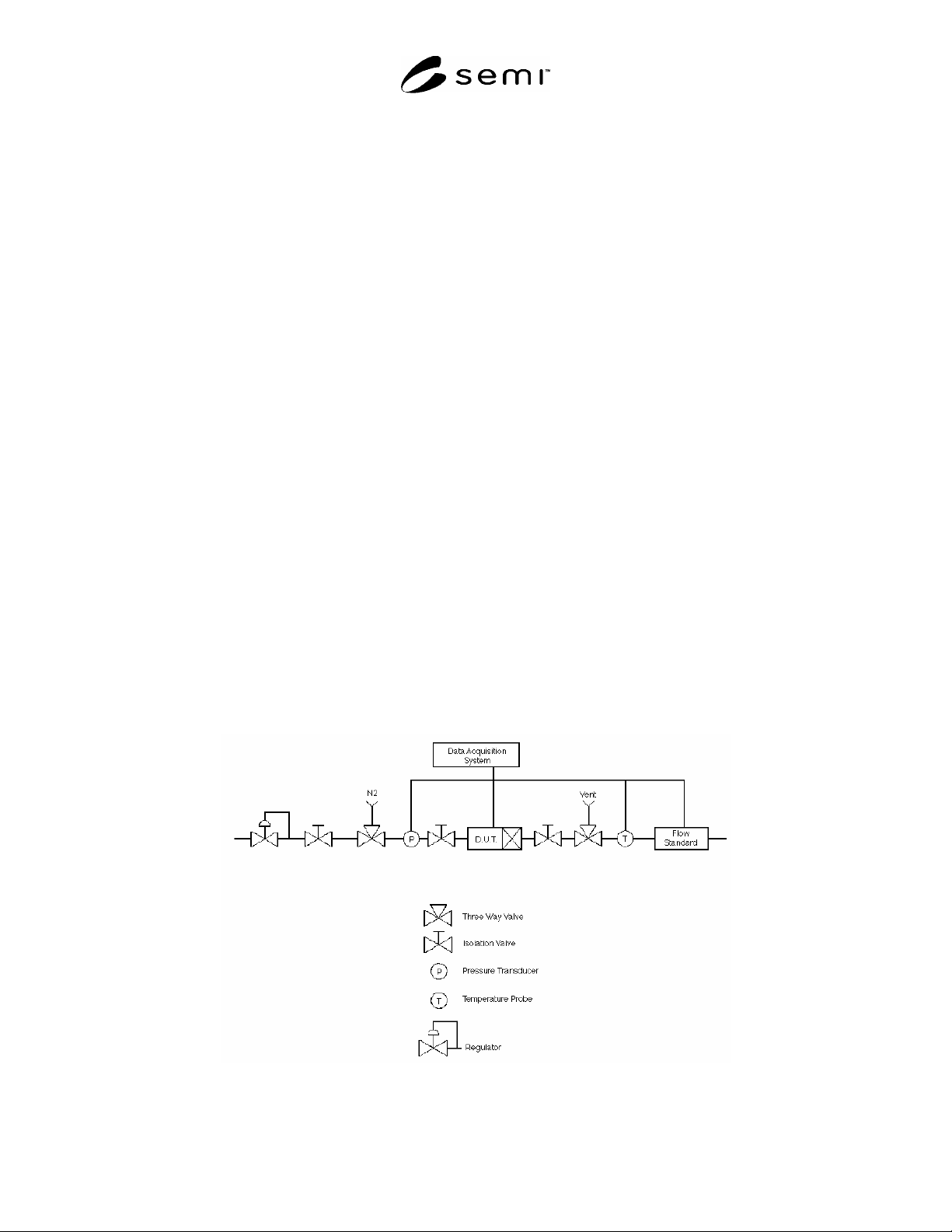
12.7 Command 100%, and establish flow, then close
the downstream isolation valve; then close the upstream
isolation valve (see Figure 1).
12.8 With both isolation valves closed, and a 100%
setpoint wait until the pressure drop across the MFC is
dissipated, ensuring a “no flow” condition through the
MFC. Dissipation of the pressure across the MFC is
indicated when the indicated flow drops to a steady
state value near zero.
12.9 After the electrical output signal has stabilized for
at least three minutes, record the MFC zero offset in
Table 1.
Figure 1
Mass Flow Controller Test Fixture
SEMI E77-1104 © SEMI 1998, 2004 4
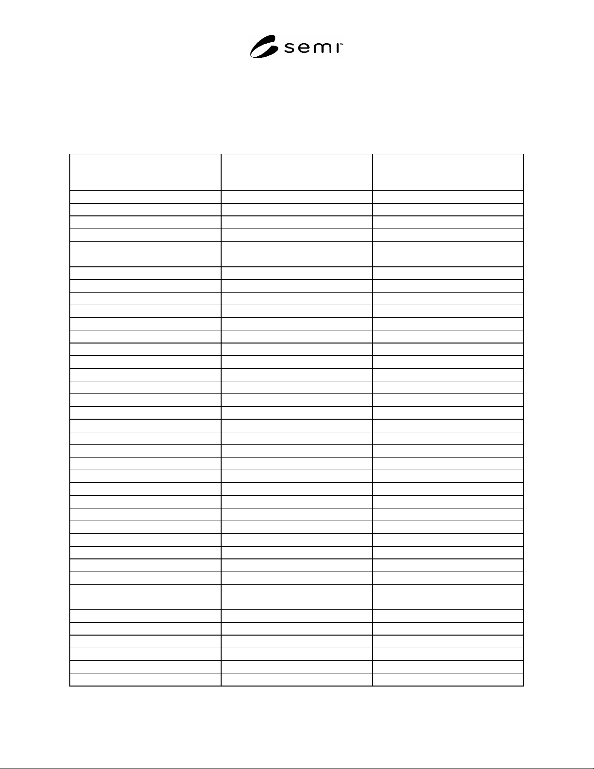
Table 1 Indicated and Actual Flow vs. Setpoint
MFC Mfg/Model/Serial # ____________________________________
Name Plate Gas/Range ____________________________________
Test Gas ____________________________________
Temp ___________ Bar ___________ Date ___________
Factory Calibration Gas ____________________________________
Column A
D.U.T. Setpoint
Indication in % F.S.
Column B
D.U.T. Flow
Indication in % F.S.
Column C
Flow Standard
Raw Data
0%
#1
0
50
60
70
80
90
100
90
80
70
60
50
40
30
10
0% __________________ 0
10
20
30
40 0
50
60
70
80
90
100
90
80
70
60
50
40
30
10
0% __________________ 0
10
20
30
40
SEMI E77-1104 © SEMI 1998, 2004 5
Column A
D.U.T. Setpoint
Indication in % F.S.
Column B
D.U.T. Flow
Indication in % F.S.
Column C
Flow Standard
Raw Data
50
60
70
80
90
100
90
80
70
60
50
40
30
10
0% __________________ 0
10
20
30
40
50
60
70
80
90
100
90
80
70
60
50
40
30
10
0% __________________ 0
10
20
30
40 0
50
60
70
80
90
100
90
80