semi合集-English.pdf - 第158页
SEMI E20-0697 © SEMI 1991, 2002 3 RELATED INFORMATION 1 NOTE: The material con tained in these application notes is no t an official part of SEMI E20 a nd is not meant to modify or supersede it in anywa y. Rather, these …

SEMI E20-0697 © SEMI 1991, 2002 2
power sources. The 24 VAC power to energize this
circuit is provided from within a main power enclosure,
so that the EMO circuit is independent of module
power. Each module EMO is connected to the chain at
its EMO interface. A momentary bypass switch, also
located at each module EMO interface, allows
separation of the module from the cluster tool without
tripping the EMO, provided that electrical power is
removed from the module by turning off the dedicated
circuit breaker (see Related Information R1-4). Jumpers
in the bypass jumper plug connect the EMO circuit in
series with contacts that open if the dedicated circuit
breaker is turned on.
6.2.2 Wiring — Copper wire used in the EMO circuits
shall be 0.82 mm
2
cross-section (#18 AWG) or larger.
6.2.3 Labeling — A label with the following legend is
to be affixed to the power distribution enclosure near
each module circuit breaker: Caution: Energizing this
circuit with the associated EMO bypass jumper plug
installed will interrupt power to the entire cluster tool.
6.3 Connection at EMO Interface
6.3.1 EMO Connector — The connector at the EMO
interface is reserved for EMO functions only. Metal
shell bayonet-type connectors are specified per MIL-C-
26500E as follows: MS24265R16B10SN on the panel,
and MS24266R16B10PN on the cable and on the EMO
bypass jumper plug. The receptacle is panel mounted at
the EMO interface and the plug is mounted on the
module EMO cable.
6.3.2 Module EMO Connector Pinouts — Pins 1 and 2
of the EMO cable plug connect across contacts in the
module EMO switch. In the receptacle, pins 1 and 2
connect to the EMO circuit and pins 3 and 4 connect
across the contacts specified in Section 6.2.1.
6.3.3 EMO Bypass Jumper Plug — Pin 1 is jumpered
to pin 4 and pin 2 is jumpered to pin 3 in the plug. This
will result in placing the contacts specified in Section
6.2.1 into the EMO circuit when the plug is installed.
NOTICE: The user’s attention is called to the
possibility that compliance with this standard may
require use of an invention covered by patent rights. By
publication of this standard, Semiconductor Equipment
and Materials International (SEMI) takes no position
respecting the validity of any patent rights asserted in
connection with any item mentioned in this standard. In
particular, users of the specification should be aware
that Drytek, Inc., A Unit of General Signal, 16 Jonspin
Road, Wilmington, MA 01887-1087, Phone: (508) 657-
3933, has neither claimed nor disclaimed that
compliance with this specification would require use of
an invention covered by one or more of its patents.
Users of this standard are expressly advised that
determination of any such patent rights, and the risk of
the infringement of such rights, are entirely their own
responsibility.
NOTICE: SEMI makes no warranties or
representations as to the suitability of the standards set
forth herein for any particular application. The
determination of the suitability of the standard is solely
the responsibility of the user. Users are cautioned to
refer to manufacturer' s instructions, product labels,
product data sheets, and other relevant literature,
respecting any materials or equipment mentioned
herein. These standards are subject to change without
notice.
By publication of this standard, Semiconductor
Equipment and Materials International (SEMI) takes no
position respecting the validity of any patent rights or
copyrights asserted in connection with any items
mentioned in this standard. Users of this standard are
expressly advised that determination of any such patent
rights or copyrights, and the risk of infringement of
such rights are entirely their own responsibility.

SEMI E20-0697 © SEMI 1991, 2002 3
RELATED INFORMATION 1
NOTE: The material contained in these application notes is not an official part of SEMI E20 and is not meant to modify or
supersede it in anyway. Rather, these notes are provided primarily as a source of information to aid in the application of the
standard. As such, they are to be considered as reference material only. The standard should be referred to in all cases.
R1-1 AC Power Distribution
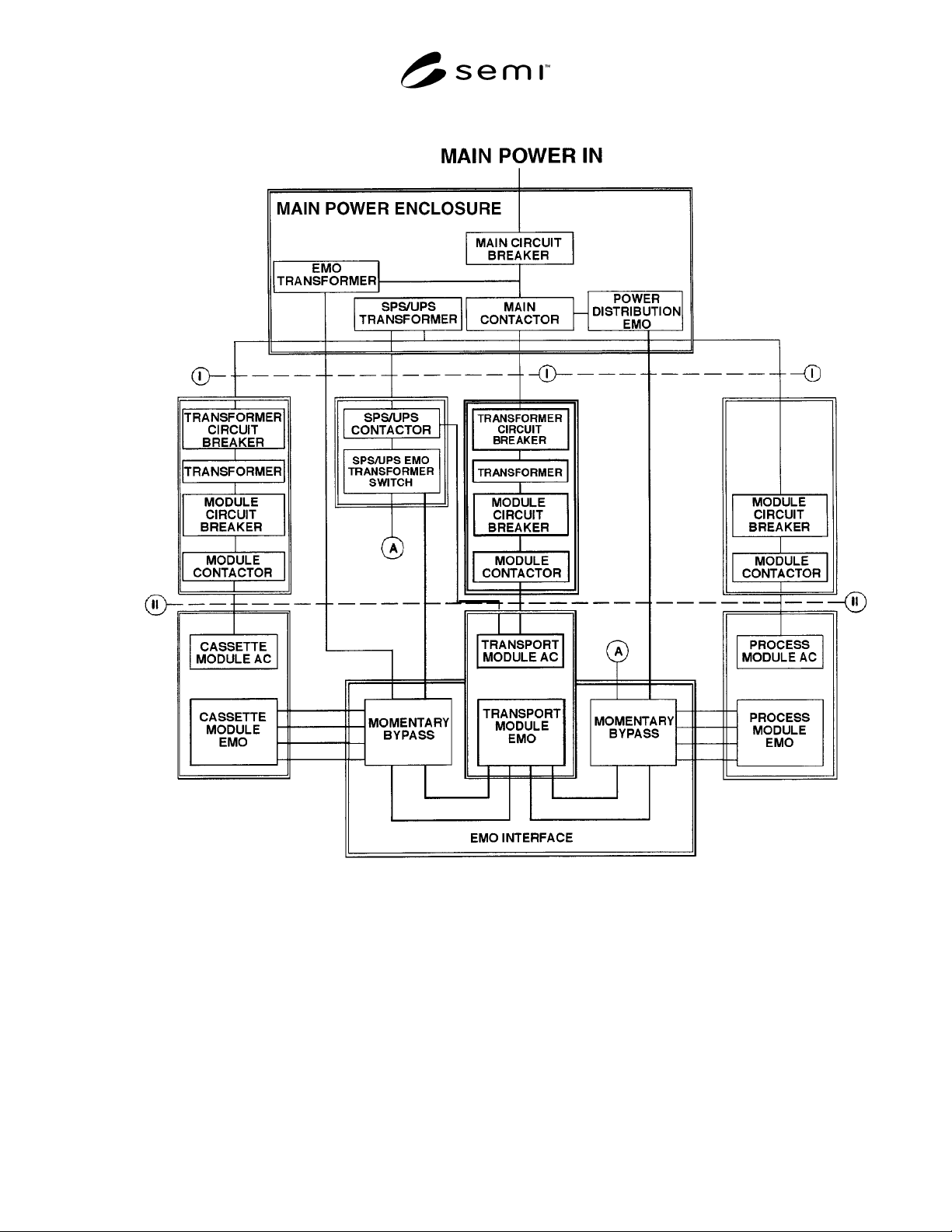
R1-1.1 One method of providing power and EMO
functions to a cluster tool is shown in Figure R1-1 (see
Section 6.1.2). A standby power supply (SPS) or
uninterruptible power supply (UPS) is included to
maintain EMO and selected cluster tool functions in the
event of main power failure. It may be desirable to
include additional circuit breakers in the main power
enclosure if individual module disconnects are needed
at level I in Figure R1-1. Disconnect at level II in
Figure R1-1 is made possible by the module circuit
breakers; SEMI E7, “Electrical Interfaces
Specification,” should be used for loads up to 10 kW.
Additional main power enclosures could be provided
for modules with heavy AC loads, provided that each
main contactor is operated by one common EMO
circuit, however, some user’s safety codes may demand
a single source of supply.
R1-2 Operation of Remote Equipment
R1-2.1 Activation of the EMO shall stop, by fail-safe
means at the tool, the delivery of potentially hazardous
energy (e.g., high voltage, laser) or hazardous material
(e.g., toxic process gas, coolant) to the cluster tool (see
Section 6.1.3).
R1-3 EMO Switch Placement
R1-3.1 The EMO switches on each module (see
Section 6.2.1) need to be placed so that they are
accessible to any person in the vicinity of the cluster
tool. Local safety codes may take precedence in matters
of EMO switch placement. The standard ensures that
each module has at least one EMO switch and that its
operation, when the module is attached, removes power
from the entire cluster tool.
R1-4 EMO Bypass
R1-4.1 Implementation — The functions, specified in
Section 4.2.1, to allow EMO bypass and to ensure that
module power is off when the EMO is removed from
the cluster tool EMO circuit, can be implemented as
shown in Figure R1-2. A relay or switch, operated in
parallel with the dedicated circuit breaker specified in
Section 6.1.2 for the module, provides 24 VAC to the
coil of a double pole relay when the circuit breaker is
de-energized. An indicator light in parallel with the coil
illuminates when the bypass is enabled and the power
to the module is off. One set of contacts of this relay is
used to enable the momentary EMO bypass switch. The
other set is connected across pins 3 and 4 of the EMO
receptacle at the EMO interface and is in the EMO
circuit when the EMO bypass jumper plug is installed.
Both sets of contacts are wired to open when voltage is
removed from the relay coil, i.e., when the circuit
breaker is closed.
R1-4.2 Module Disconnect — The dedicated circuit
breaker (see Section 6.2.1) to the module must be
turned off prior to disconnect. This causes the contacts
in series with the momentary EMO bypass switch to
close, rendering it operational. At this point, the EMO
switch on the module is still in the cluster tool EMO
circuit. To disconnect, the operator holds in the EMO
bypass switch while removing the module EMO plug
from the EMO interface and then connecting the EMO
bypass jumper plug. The momentary bypass switch can
then be released.
R1-4.3 Module Connect — To connect a module, the
dedicated circuit breaker (see Section 6.2.1) must be off
at the power distribution point to the module. The
power cable may be attached to the module at this time.
The operator holds in the momentary bypass switch
while disconnecting the EMO bypass jumper plug from
the EMO interface and connecting the module EMO
Plug. The momentary bypass switch can then be
released. Power cannot be applied to the module unless
the EMO is connected (as shown in Figure R1-2).
R1-5 Additional Documents and References
In implementing the standard, documents that may
provide additional guidance include:
R1-5.1 SEMI Document
SEMI S2 — Safety Guidelines for Semiconductor
Manufacturing Equipment
R1-5.2 Other Documents
International Electrotechnical Commission (IEC)
Standard 204, Sections 1, 2 and 3.
(U.S.) National Electrical Code (NEC).
2
2 National Fire Protection Association, Batterymarch, Quincy, MA
02269.
SEMI E20-0697 © SEMI 1991, 2002 4
Figure R1-1
Example: AC Distribution/EMO Block Diagram