semi合集-English.pdf - 第4022页
SEMI F49-0200 © SEMI 2000 8 8 Related Documents 8.1 SEM I Standards Under deve lopment. 8.2 C ENELEC Standard 2 EN 50082-2 — Electrom agnetic co mpatibility - Generic imm unit y st andard, Part 2. Indus trial enviro n me…
SEMI F49-0200 © SEMI 20007
factors in determining the sag response of many
common devices.
138kV (L-L Nominal)
φ
C
φ
B
φ
A
Substation Transformer
First Step-down Transformer
Second Step-down Transformer
12.47 kV (L-L Nominal) 7.2 kV (L-N Nominal)
480 or 208 volt (L-L) 277 or 120 volt (L-N)
208 volt (L-L) 120 volt (L-N)
Sag Voltage
(% of Normal)
V
AB
58%
V
BC
100%
V
CA
58%
Sag Voltage
(% of Normal)
V
AB
88%
V
BC
88%
V
CA
33%
Sag Voltage
(% of Normal)
V
AN
58%
V
BN
100%
V
CN
58%
Sag Voltage
(% of Normal)
V
AB
58%
V
BC
100%
V
CA
58%
Sag Voltage
(% of Normal)
V
AB
88%
V
BC
88%
V
CA
33%
Sag Voltage
(% of Normal)
V
AN
88%
V
BN
88%
V
CN
33%
Sag Voltage
(% of Normal)
V
AN
58%
V
BN
100%
V
CN
58%
φ
Α
L-G Fault
F
A
C
I
L
I
T
Y
U
T
I
L
I
T
Y
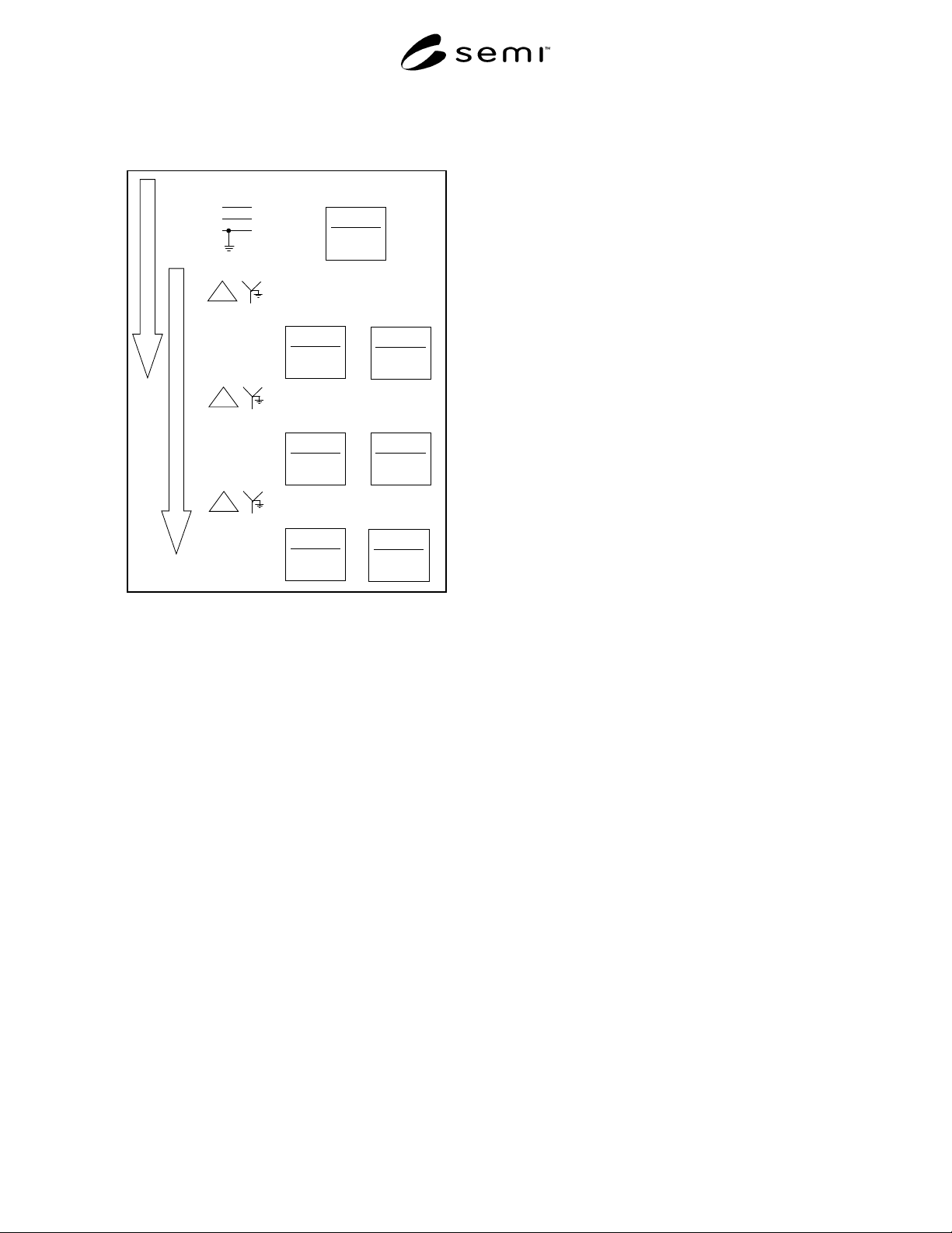
Figure 4
Example of Voltage Sag Levels during a Single Line
to Ground Fault
7.6.5.7 Figure 4 illustrates the importance of phase
relationships in the sag response of a 120-volt control
circuit emergency off (EMO) relay which is connected
to phase A (or phase B) in a 208-volt facility
distribution system derived with only one low voltage
transformation. In this example the voltage sags to only
88% of nominal on these phases, but drops to 33% of
nominal on phase C. The industry specification for
semiconductor processing equipment voltage sag
immunity does not specify that equipment ride-through
a sag to 33% of nominal voltage.
7.6.5.8 If two low voltage transformations were used
to derive the 208-volt facility system (see Figure 4),
phase B voltage would be unaffected during the utility
voltage sag, but phases A and C would sag to 58% of
nominal. Industry standards typically require
equipment to ride-through a sag of this depth.
However, a tolerance designed into the facility system
may be necessary to provide adequate system
protection.
7.7 Power Enhancing and Conditioning Strategies
7.7.1 While it is desirable to reduce and eliminate
battery storage devices provided by equipment
suppliers with individual pieces of process equipment,
battery storage devices may be appropriate as a
centralized or distributed part of a facilities distribution
system (when evaluated in a systems approach to power
enhancement and conditioning).
7.7.2 Facility power systems enhancements should be
examined on a case-by-case approach to determine the
appropriate measure of power conditioning to be
applied. In general, the following types of equipment
are frequently used to mitigate the effects of utility
voltage sag events in semiconductor factories.
• Constant voltage transformers (typically applied on
control systems)
• Diesel engine based uninterruptible power supplies
(UPS)
• Magnetic synthesizers
• Motor-generators
• Rotary UPS
• Static UPS
• Static transfer switches with alternate power
systems
7.7.3 Other power enhancement techniques and
equipment available for use in facilities electrical
distribution systems include but are not limited to the
following:
• Capacitors for voltage regulation,
• Filters for power conditioning,
• High resistance grounding,
• Isolation of electrical circuit from other loads,
• Power line conditioners,
• Primary and secondary selective rather than radial
distribution systems,
• Super-conducting magnetic energy storage
systems,
• Transformer load tap changers, and
• Voltage regulators.
7.7.4 Power enhancement and conditioning equipment
can be applied at selected equipment components,
selected distribution circuits, or selected distribution
buses. For power conditioning equipment application
guidelines see IEEE 1100 and 1346.

SEMI F49-0200 © SEMI 2000 8
8 Related Documents
8.1 SEMI Standards
Under development.
8.2 CENELEC Standard
2
EN 50082-2 — Electromagnetic compatibility -
Generic immunity standard, Part 2. Industrial
environments.
8.3 IEC Standard
3
IEC 61000-4-11 — Electromagnetic Compatibility
(EMC) - Part 4: Testing and Measuring Techniques -
Section 11: Voltage Dips, Short Interruptions and
Voltage Variations Immunity Tests
8.4 IEEE Standards
1
IEEE Std 493 — IEEE Recommended Practice for the
Design of Reliable Industrial and Commercial Power
Systems
IEEE Std 1250 — IEEE Guide for Service to
Equipment Sensitive to Momentary Voltage
Disturbances
NOTE 2: As listed or revised, all documents cited shall be the
latest publications of adopted standards.
NOTICE: SEMI makes no warranties or
representations as to the suitability of the guides set
forth herein for any particular application. The
determination of the suitability of the guide is solely the
responsibility of the user. Users are cautioned to refer
to manufacturer’s instructions, product labels, product
data sheets, and other relevant literature respecting any
materials mentioned herein. These guides are subject to
change without notice.
The user’s attention is called to the possibility that
compliance with this guide may require use of
copyrighted material or of an invention covered by
patent rights. By publication of this guide, SEMI takes
no position respecting the validity of any patent rights
or copyrights asserted in connection with any item
mentioned in this guide. Users of this guide are
expressly advised that determination of any such patent
rights or copyrights, and the risk of infringement of
such rights, are entirely their own responsibility.
2 European Committee for Electrotechnical Standardization
(CENELC), Rue de Stassart, 35, B - 1050 Brussels
3 International Electrotechnical Commission (IEC), 3 rue de
Varembé, PO Box 131, 1211 Geneva 20, Switzerland
Copyright by SEMI® (Semiconductor Equipment and Materials
International), 3081 Zanker Road, San Jose, CA 95134. Reproduction o
f
the contents in whole or in part is forbidden without express written
consent of SEMI.

SEMI F50-0200 © SEMI 20001
SEMI F50-0200
GUIDE FOR ELECTRIC UTILITY VOLTAGE SAG PERFORMANCE FOR
SEMICONDUCTOR FACTORIES
This guide was technically approved by the Global Facilities Committee and is the direct responsibility of the
North American Facilities Committee. Current edition approved by the North American Regional Standards
Committee on December 15, 1999. Initially available on www.semi.org February 2000; to be published
February 2000.
1 Purpose
1.1 This guide provides a framework for
semiconductor and flat panel display (FPD)
manufacturers and their electric utility service providers
to minimize the effect of voltage sag events on
semiconductor processing. In particular, this guide
focuses on electric utility power quality performance
goals that are complementary to voltage sag immunity
levels for semiconductor processing equipment and
facilities infrastructure equipment (see Figure 1).
Recommendations for measuring and evaluating
voltage sag performance, evaluating utility system
enhancements, and implementation of a continuous
improvement process are included since no electric
utility industry standards exist.
1.2 Utility systems are designed, constructed, and
operated to meet utility industry regulations and
requirements. One important requirement for
semiconductor factories is power system reliability.
Utilities measure reliability in minutes of voltage
outages per customer per year. Semiconductor factories
require a high level of power system reliability, any
service outage is usually unacceptable. A second
important requirement is power quality. Power quality
relates to disturbed voltage waveforms, not outages.
When utilities implement measures to increase power
system reliability, power quality can be adversely
affected. The structured approach defined in this guide
can achieve high levels of power quality without
sacrificing power reliability.
1.3 The intent of this guide is to help semiconductor
manufacturers achieve both high levels of power
reliability and power quality from energy utility
providers. By becoming familiar with the cause and
effect relationships of voltage sag events on the utility’s
side of the electric meter, semiconductor manufacturers
and electric utilities can work together to pursue
efficient solutions for improved voltage sag ride-
through in semiconductor factories.
2 Scope
2.1 The scope of this guide extends beyond a
discussion of typical electric utility reliability and
quality improvement techniques to developing a
continuous improvement process for electric utility
voltage sag performance (depicted graphically in Figure
2). Factors in this process include the following:
• Define desired performance criteria by setting
goals for voltage sag event duration and magnitude
(see Section 6.1).
• Measure performance for both proposed and
existing semiconductor factory sites (see Section
6.2).
• Summarize voltage sag event data and identify the
impact on semiconductor processing and facilities
infrastructure equipment (see Section 6.3).
• Recommend improvements that include
consideration of cost, benefit, and risk.
Improvements can include corrective action to
eliminate system faults, changes to service
configurations, and power enhancements (see
Section 6.4).
• Select and implement improvements. Establish a
continuous improvement process (see Section 6.5).
2.2 For the purposes of this document, the term
Electric Utility refers to energy service providers (that
sell energy to semiconductor manufacturers) and/or
electric transmission and distribution providers (that
deliver energy through their power lines).
2.3 This guide does not purport to address safety
issues, if any, associated with its use. It is the
responsibility of the users of this guide to establish
appropriate safety and health practices and determine
the applicability of regulatory limitations prior to use.