semi合集-English.pdf - 第2113页
SEMI E54.14-0305 © SEMI 2005 7 IO device Sub slot 0 Sub slot m ... Slot0 Slot 1 carrie s Module x Sub slot 0 Sub slot m ... Record Data Diag nosis Alarm IO Data Subslot 0 Sub slot m Context Slot n carr ie s Modu le y Fig…

SEMI E54.14-0305 © SEMI 2005 6
6.4 Data Link Layer — Layer 2
6.4.1 Data Transfer
6.4.1.1 The Data Link Layer provides the functions for sending and receiving data over the network. Protocol Data
Units (PDU) are packaged, delivered, and checked. Checks are used to guard against Line Protocol Errors (e.g.,
frame, overrun, and coding violations). IEEE 802.3 Data Link MAC sublayer is the preferred Data link technology
of PROFINET. If an accepted data link standard other than IEEE 802.3 is being used it has to be clearly specified in
the product documentation.
6.4.1.2 A PDU is restricted to 1500 bytes. A protocol overhead of 28 Bytes is needed for addressing, error
detection and protocol selection.
6.4.2 Conveyance of Data
6.4.2.1 In IEEE 802 networks bridges (switches) are used to transport data. These bridge functions are defined in
IEEE 802.1D and IEEE 802.1Q (priority options). Real time extensions can be used to enhance performance and
availability of bridged networks.
6.5 Network Layer — Layer 3
6.5.1 While real time data transfer uses a protocol with no network layer, all other services are using IP (Internet
Protocol) as network layer.
6.6 Transport Layer — Layer 4
6.6.1 All non-real time services are using UDP (User Datagram Protocol) as transport layer.
6.7 Session Layer — Layer 5
6.7.1 There is no distinct Session Layer in this CDM.
6.8 Presentation Layer — Layer 6
6.8.1 There is no distinct Presentation Layer in this CDM. The Encoding is part of the application layer.
6.9 Application Layer — Layer 7
6.9.1 The PROFINET IO application layer is structured in a so called service definition and protocol specification.
The service definition uses an object orientated approach and specifies the services for remote access and local
functions together with their objects (the ASE is a class definition of these objects). The protocol specification
includes both coding and state machines.
6.9.2 Service Definition
6.9.2.1 Application layer services are structured to reflect the needs of flexible configurable automation devices. A
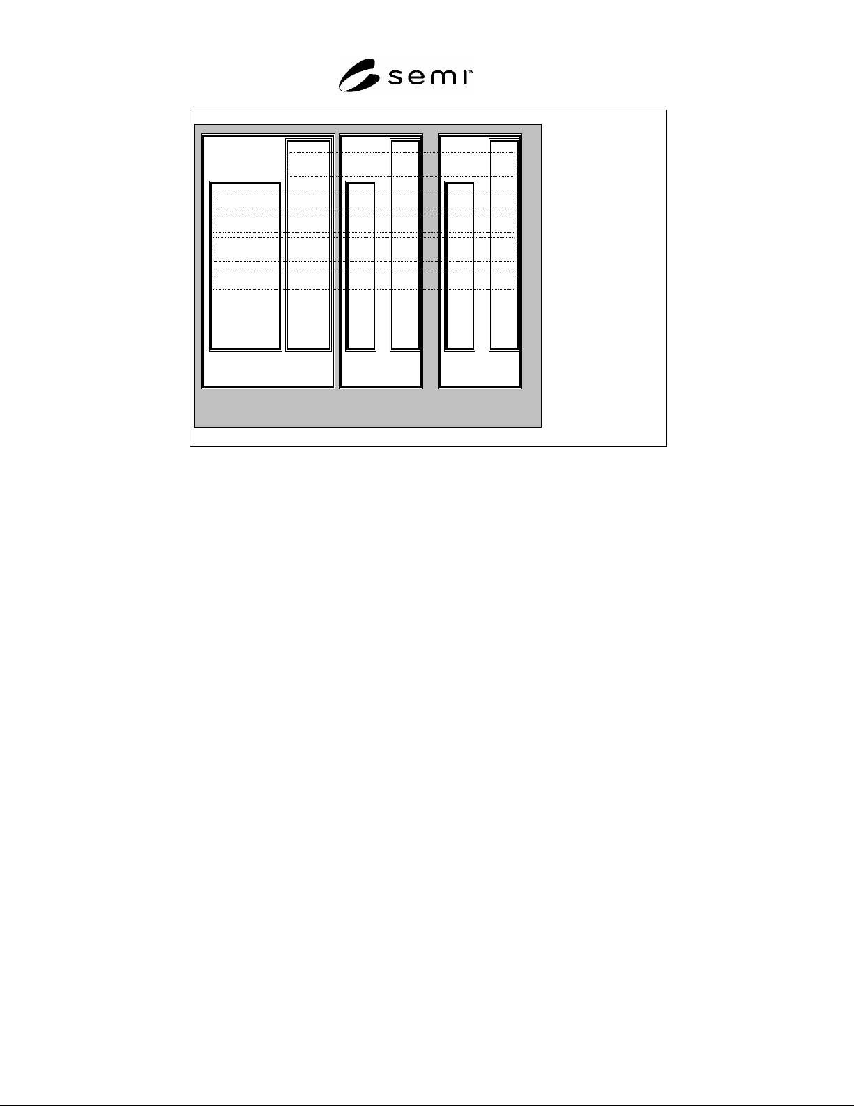
Device consists of a set of modules that are placed in slots (see Figure 2). Modules are addressed uniquely by the
slot number. The module view can be a hardware oriented or reflects the software structure of the IO Device.
6.9.2.2 Each module contains submodules that contain objects of different classes. Submodules are the addresses of
the submodules.
6.9.2.3 Slot 0 is used to address the IO Device itself. Subslot 0 represents the module and contains no IO Data.
The other object classes can have instances scattered over the modules and their submodules addressed by slots and
their subslots respectively. Each submodule (except submodule 0) can contain IO Data, Context parameter,
Diagnosis information, Record Data and Alarms. Record Data is a generic class which can contain different
application specific parameters accessible by read and write services. There is a set of identification and
maintenance parameters defined in a PROFIBUS Guideline that are mandatory within PROFINET.
SEMI E54.14-0305 © SEMI 2005 7
IO device
Sub
slot
0
Sub
slot
m
...
Slot0
Slot 1 carries
Module x
Sub
slot
0
Sub
slot
m
...
Record Data
Diagnosis
Alarm
IO Data
Subslot 0
Sub
slot
m
Context
Slot n carries
Module y
Figure 2
Device Model
6.9.2.4 Object classes are defined for:
IO Data for periodic reporting,
Context for configuration,
Diagnosis for event collection,
Record Data for polled access, and
Alarms for asynchronous event reporting.
A set of services are defined for these object classes.
6.9.2.5 IO Data are handled mainly by buffered services which allow decoupling between application and
communication. Client/Server service structure (request/response) is used for Context for configuration, Diagnosis
for event collection, Record Data for polled access and Alarms for asynchronous event reporting.
6.9.2.6 Cyclic functionalities offered in PROFINET IO:
exchange of IO data with related IO devices
6.9.2.7 Acyclic functionalities offered in PROFINET IO:
read diagnosis from IO devices
configuration of IO devices
write parameter data to IO devices (startup or application parameter)
treatment of configuration and diagnosis requests of an engineering device
initiate connections to IO devices by means of context management
acyclic access to record data of IO devices
treatment of alarms from IO devices
SEMI E54.14-0305 © SEMI 2005 8
sending of alarms to IO devices
6.9.3 Protocol Specification
6.9.3.1 An IO device has no IP-address and logical name when it is shipped.
6.9.3.2 A set up procedure has to allocate name and IP-address prior to operation.
6.9.3.3 To access an IO Device a controller has to establish the context first with a connect service. A check is
done to ensure that the appropriate device type with the required resources is accessed. Resources can be locked
with the connect service.
6.9.3.4 After a positive confirmation of the connect service the IO device may be loaded with the parameter
required by the controller application (e.g. warning limits, measure range, filter time). A control service is issued at
the end of parameterization.
6.9.3.5 There is a control service indicating that the IO Device application is ready to enter the operate state. The
start up is completed with this service.
6.9.3.6 After this start up procedure the data exchange of IO data can be done and alarms can be signaled from the
IO Device to the IO Controller. The IO Controller can invoke services to read and write record data that contain all
kind of information e.g. produced units, calibration information, and batch information.
6.9.3.7 A Release service will terminate the context.
6.9.3.8 A context is monitored by the receipt of Input Data at the IO controller and by the receipt of Output Data at
the IO device site. A timeout error of one timer unit is allowed which makes it possible to use a single timer
resource with granularity in the range of a millisecond.
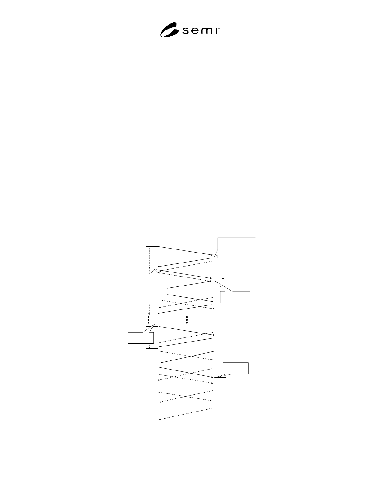
6.9.3.9 Figure 3 shows a sequence diagram of the start up procedure.
IO Controller
IO Device
CM_Connect.req()
CM_Connect.rsp (+)
Write_Record.req()
Write_Record.rsp (+)
IO Controller-
Timeout
Establish
Provider/Consumer/
Alarm-Statemachine
Start Provider
Start Consumer
with Monitoring
Write_Record.req()
Write_Record.rsp (+)
CControl.req()
CControlrsp()
Outputs
Inputs
DControl.req()
DControl.rsp(+)
Start Alarm-
Statemachine
Start Alarm-
Statemachine
Establish
Provider/Consumer/
Alarm- Statemachine
Start Provider
Start Consumer with
Monitoring
Figure 3
Start Up Sequence