semi合集-English.pdf - 第5875页
SEMI P36-0600 © SEMI 2000 2 6.2.2.2.2 The m arkers made on the spec i m en stage should show the X- an d Y-direct ion of s pecimen-stag e movement, and th e a ngle between the tw o markers should be 90° ± 0.1° (See Fi gu…

SEMI P36-0600 © SEMI 20001
SEMI P36-0600
GUIDELINE OF MAGNIFICATION REFERENCE FOR CRITICAL
DIMENSION MEASUREMENT SCANNING ELECTRON MICROSCOPES
(CD-SEMS)
This guideline was technically approved by the Global Metrology Committee and is the direct responsibility
of the Japanese Metrology Committee. Current edition approved by the Japanese Regional Standards
Committee on March 1, 2000. Initially available at www.semi.org May 2000; to be published June 2000.
1 Purpose
1.1 The purpose of this guideline is (1) to define
common and important specifications of magnification
references which are used for calibrating magnifications
of critical dimension measurement scanning electron
microscopes (CD-SEMs), and as the result (2) to
provide magnification references which are easy for
anyone to use.
2 Scope
2.1 It is preferable that design, manufacture and
purchase specifications for CD-SEM magnification
references conform to this guideline.
2.2 This standard does not purport to address safety
issues, if any, associated with its use. It is the
responsibility of the users of this standard to establish
appropriate safety and health practices and determine
the applicability of regulatory limitations prior to use.
3 Referenced Standards
3.1 None.
4 Terminology
4.1 CD-SEM magnification refere nce
a CD-SEM
magnification reference is defined as a standard for
calibrating magnifications of a said CD-SEM through
mounting the standard on the specimen stage,
measuring the dimensions of reference patterns formed
on the standard, determining the difference between the
measurement value and the true or reference value of
the reference patterns, and adjusting the CD-SEM
parameters to bring the difference zero.
4.1.1 There are two types of CD-SEM magnification
references: one is a wafer on which reference patterns
are formed; another is a chip on which reference
patterns are formed. Hereinafter, the former will be
referred to as “wafer-type magnification reference,” and
the latter will be referred to as “chip-type magnification
reference.”
4.2 edge roughness Edge rough ness refers to edge
variations seen in the SEM images, and is defined as
the distance, within a field of view, between the peak
line and the valley line, where the peak line means the
line which runs through the highest peak and is parallel
to the pattern-edge mean line, the valley line means the
line which runs through the lowest valley and is parallel
to the pattern-edge mean line, and the pattern-edge
mean line conforms to the expected pattern-edge line.
Here, a peak is the tip of a convex section, and a valley
is the deepest part of a concave section (See Figure 1).
5 Ordering Information
5.1 Specify whether a said CD-SEM magnification
reference is a wafer-type magnification reference or a
chip-type magnification reference.
6 Requirements
6.1 CD-SEM Magnification References and Their
Structure
6.1.1 CD-SEM Magnification References are either
wafer type or chip type. Chip types are composed of a
chip (or chips) and a stub to hold the chip (or chips).
Wafer type include a 'drop-in' wafer which is a wafer
with a thinned section where a die with the reference
calibration pattern can be dropped in.
6.2 Shape, Size and Mounting Method of CD-SEM
Magnification References
6.2.1 Shape and size of wafer-type magnification
references, and method of mounting them on the
specimen stages in CD-SEMs must follow the shape,
size and mounting method of product wafers.
6.2.2 Shape and size of chip-type magnification
references, and method of mounting them on the
specimen stages of CD-SEMs are defined as follows:
6.2.2.1 Size and shape of chip-type magnification
references: See Figure 2.
6.2.2.2 Mounting method of chip-type magnification
references:
6.2.2.2.1 A magnification reference should be
mounted on a specimen stage as markers made on the
stub fit in markers made on the specimen stage, and be
fixed by using a screw. The markers made on the stub
should show the direction of reference patterns at an
accuracy of within ± 1°.

SEMI P36-0600 © SEMI 2000 2
6.2.2.2.2 The markers made on the specimen stage
should show the X- and Y-direction of specimen-stage
movement, and the angle between the two markers
should be 90° ± 0.1° (See Figures 2 and 3).
6.2.2.3 Chip surface height for chip-type
magnification references:
6.2.2.3.1 The height of chip surface (or reference
pattern surface) from the specimen stage surface should
be 1.7 ± 0.05 mm as the magnification reference is
mounted on the specimen stage.
6.3 Materials for Magnification R eferences
Materials for magnification references must be non-
magnetic and conductive.
6.3.1 Wafers for wafer-type magnifi cation references
and chips for chip-type magnification references are
preferable to be silicon.
6.3.2 Materials of the stub for chip-t ype magnification
references are preferable to be aluminum, copper, or
carbon.
6.4 Properties of Magnification Reference Pattern
6.4.1 Reference patterns do not change or degrade in
use.
6.4.2 The block area of reference patterns (or every
block area, in the case where there are some reference
pattern blocks) must be larger than 100 µm × 100 µm,
and the block should be placed so that it is easily
recognizable.
6.4.3 The pattern-edge roughness must be within the
calibration uncertainty described in Section 6.5.5.
6.5 Report
6.5.1 Suppliers of CD-SEM magnification references
must report the following to the purchaser.
6.5.2 Wafer material for wafer-type magnification
references, or chip and stub materials for chip-type
magnification references: e.g., silicon chip, aluminum
stub, etc.
6.5.3 Type of reference patterns: e.g., dense lines, etc.
6.5.4 Figures and/or pictures of the reference patterns
with pattern dimensions which show top and/or cross
sectional view.
6.5.5 Calibration uncertainty of reference patterns:
e.g., line pitch 180
± 1 nm at 95% confidence level, etc.
6.5.6 Traceability and its certification organization,
and measurement method used for deciding the
calibration uncertainty of reference patterns: e.g., the
uncertainty was decided in terms of mean value and
variation obtained by means of a precise diffraction
angle measurement using a He-Cd laser beam of a 2
mm spot diameter, and was certified by NMI (National
Metrology Institute), etc.
NOTE 1: Traceability is the property of the calibration of the
reference patterns whereby it can be related to stated
references, usually national or international standards, through
an unbroken chain of comparison of all having stated
uncertainties. Refer to the international vocabulary of basic
and general items in metrology, ISO, 1993, 60 p., ISEN 92-67
01075-1.
6.5.7 Applicable magnification range: e.g., 50k×–
200k×, etc.
6.5.8 Notices of caution for cleaning and maintenance:
e.g., whether cleaning is possible or not, and if possible,
the process of cleaning, procedures for storage, etc.
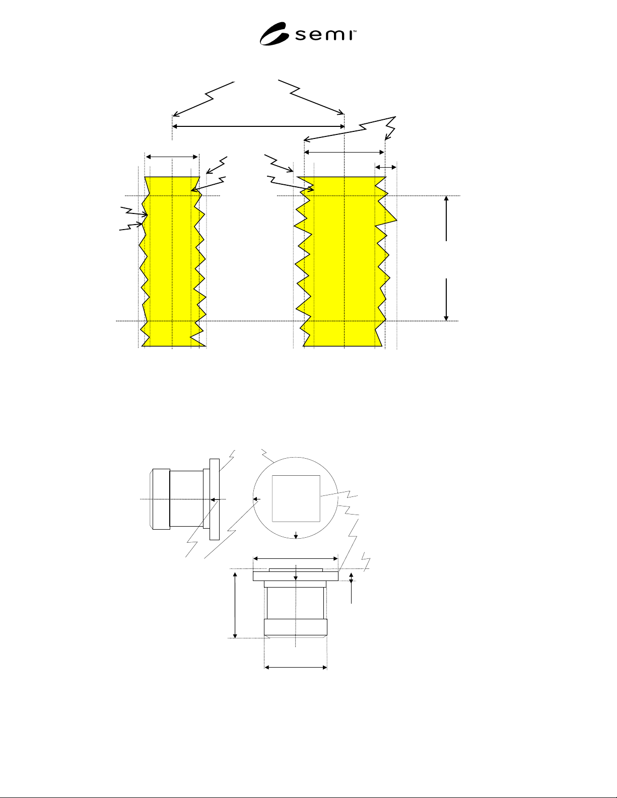
SEMI P36-0600 © SEMI 20003
center-to-center pitch
centerline
pattern edge mean line
or
least squares best fit line
linewidth
peak-to-peak edge
roughness
defined measurement length
segment
linewidth
peak line
valley line
peak
valley
NOTE 1: The figure ignores that fact that the SEM image is gray-scale and not black and white. Use the same intensity threshold
setting for measuring pitch as for line width The center-to-center pitch averaged over the measurement length segment is to be
certified and used for SEM magnification calibration
Figure 1
Definition of Edge Roughness
chip
stub
chip surface*
φ15
≈10.5
1.7±0.05
−0.032
−0.050
marker
stub
≈
φ
17
* The flatness of the chip
surface to the specimen stage
surface could be automatically
determined by setting the
magnification reference on the
specimen stage.
Figure 2
Shape and size of chip-type magnification reference: unit mm