semi合集-English.pdf - 第647页
SEMI E85-0705 © SEMI 1999, 2005 1 SEMI E85-0705 SPECIFICATI ON FOR PHYSICAL AMHS STOCKER TO INTERBAY TRANSPORT SYSTEM INTEROPERABILITY This specification was technica lly approved by t he global Physical Interfaces &…
SEMI E84-0305 © SEMI 1999, 2005 44
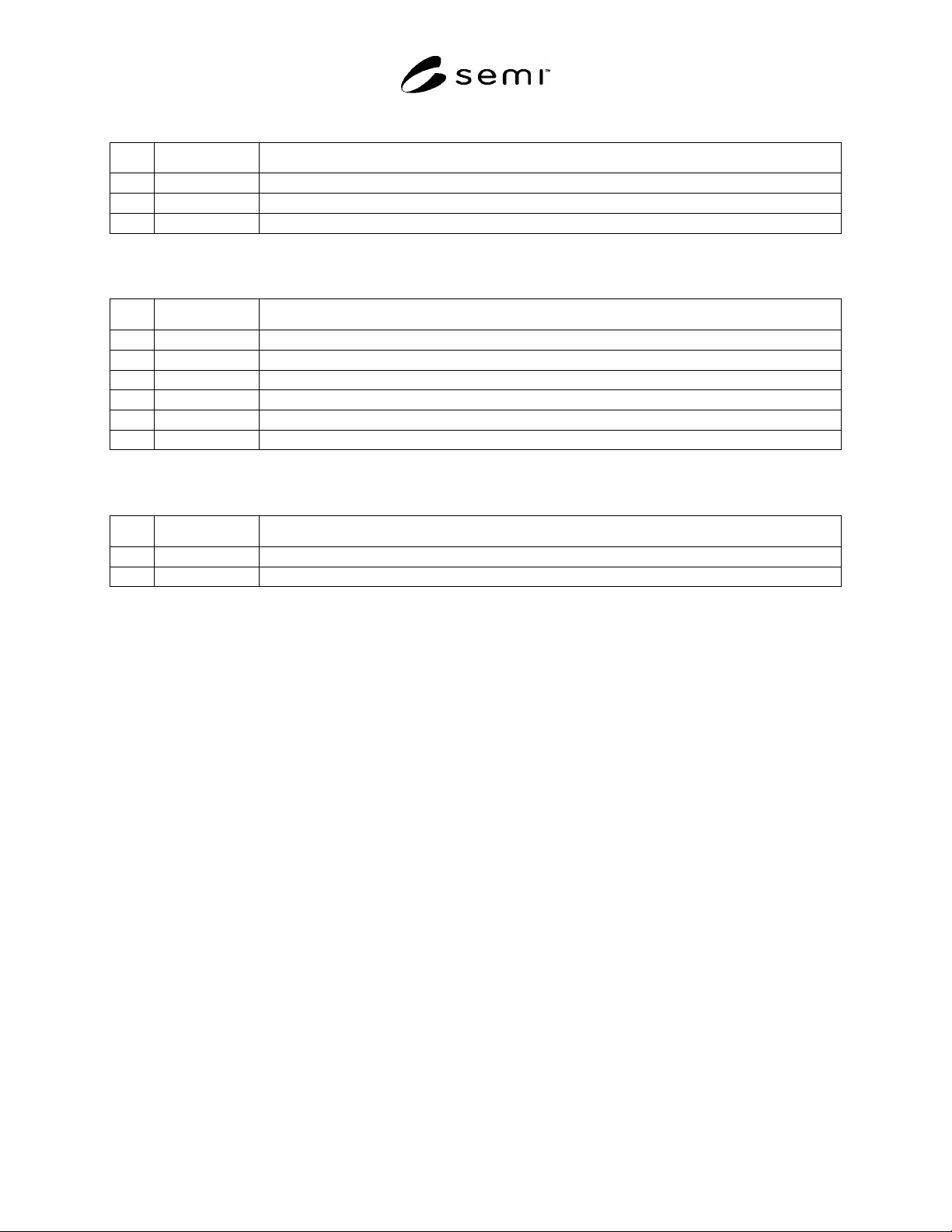
Table A1-8 Example Active Equipment Error Messages
No. Timer Name Equipment Error Message
1 TA1 TA1 Timeout – L_REQ/U_REQ signal did not turn ON within specified time. (TA1 = xxx)
2 TA2 TA2 Timeout – READY signal did not turn ON within specified time. (TA2 = xxx)
3 TA3 TA3 Timeout – READY signal did not turn OFF within specified time. (TA3 = xxx)
#1
“xxx” refers to the time in seconds that the specific timer was set to.
Table A1-9 Example Passive Equipment Error Messages
No. Timer Name Equipment Error Message
1 TP1 TP1 Timeout – TR_REQ signal did not turn ON within specified time. (TP1 = xxx)
2 TP2 TP2 Timeout – BUSY signal did not turn ON within specified time. (TP2 = xxx)
3 TP3 TP3 Timeout – Carrier was not detected/removed within specified time. (TP3 = xxx)
4 TP4 TP4 Timeout – BUSY signal did not turn OFF within specified time. (TP4 = xxx)
5 TP5 TP5 Timeout – VALID signal did not turn OFF within specified time. (TP5 = xxx)
6 TP6 TP6 Timeout – VALID signal did not turn ON within specified time. (TP6 = xxx)
#1
“xxx” refers to the time in seconds that the specific timer was set to.
Table A1-10 Example Delay Timer Error Messages
No. Timer Name Equipment Error Message
1 TD0 TD0 Timeout – VALID signal did not turn ON within specified time. (TD0 = xxx)
2 TD1 TD1 Timeout – VALID signal did not turn ON within specified time. (TD1 = xxx)
#1
“xxx” refers to the time in seconds that the specific timer was set to.
NOTICE: SEMI makes no warranties or representations as to the suitability of the standards set forth herein for any
particular application. The determination of the suitability of the standard is solely the responsibility of the user.
Users are cautioned to refer to manufacturer’s instructions, product labels, product data sheets, and other relevant
literature respecting any materials mentioned herein. These standards are subject to change without notice.
The user’s attention is called to the possibility that some implementations of this standard may involve use of
inventions covered by U.S. patents 4,306,292 and other patents issued or pending, held by Texas Instruments
Incorporated. By publication of this standard, SEMI takes no position respecting either the applicability or the
validity of these or other patent rights asserted in connection with any item mentioned in this standard. Users of this
standard are expressly advised that determination of any such patent rights, and the risk of infringement of such
rights, are entirely their own responsibility.
Copyright by SEMI® (Semiconductor Equipment and Materials
International), 3081 Zanker Road, San Jose, CA 95134. Reproduction of
the contents in whole or in part is forbidden without express written
consent of SEMI.

SEMI E85-0705 © SEMI 1999, 2005 1
SEMI E85-0705
SPECIFICATION FOR PHYSICAL AMHS STOCKER TO INTERBAY
TRANSPORT SYSTEM INTEROPERABILITY
This specification was technically approved by the global Physical Interfaces & Carriers Committee. This
edition was approved for publication by the global Audits and Reviews Subcommittee on April 7, 2005. It
was available at www.semi.org in June 2005 and on CD-ROM in July 2005. Originally published June 1999;
previously published November 2001.
1 Purpose
1.1 This specification defines the dimensional requirements for the interbay load ports of 300 mm AMHS
equipment. It is intended to promote a list of required features and dimensions that define the physical interfaces
between different types of interbay equipment, to facilitate the use of different automated transport systems in order
to meet the different material handling requirements found throughout the factory. This is done by defining six
options of interfaces that both the stocker and interbay transport system must comply with. Options defined are as
follows:
Option A: Active transport loads a carrier to an internal stocker position
Option B: Active transport loads a carrier to an external stocker position
Option C: Passive transport presents a carrier to an internal stocker position
Option D: Passive transport presents a carrier to an external stocker position (kinematic coupling pin pick-up)
Option E: Passive transport presents a carrier to an external stocker position (conveyor flange pick-up)
Option F: Passive transport presents a carrier to an external stocker position for pickup with either (a) all 3
kinematic pins, (b) all 3 secondary kinematic pins or (c) top robotic flange. Carrier is oriented with front of
carrier perpendicular to load face plane.
2 Scope
2.1 This is a standard covering physical interface of 300 mm AMHS interbay equipment only. Similar
requirements covering 300 mm AMHS intrabay equipment are covered in SEMI E15.1.
2.2 This specification does not purport to address safety issues, if any, associated with its use. It is the
responsibility of the users of this specification to establish appropriate safety and health practices and determine the
applicability of regulatory limitations prior to use.
3 Limitations
3.1 This standard does not specify that every type of 300 mm stocker has to interface with every type of 300 mm
interbay transport system. It only specifies six different options of physical interface. Within any option however,
all stockers must be able to physically interface with all interbay transports. This standard only specifies single
carrier handoff and not dual simultaneous handoffs as implied by the dimensions in the rest of this document.
4 Referenced Standards and Documents
4.1 SEMI Standards
SEMI E1.9 — Mechanical Specification for Cassettes Used to Transport and Store 300 mm Wafers
SEMI E15 — Specification for Tool Load Port
SEMI E15.1 — Specification for 300 mm Tool Load Port
SEMI E47.1 — Provisional Mechanical Specification for Boxes and Pods Used to Transport and Store 300 mm
Wafers

SEMI E85-0705 © SEMI 1999, 2005 2
SEMI E57 — Mechanical Specification for Kinematic Couplings Used to Align and Support 300 mm Wafer
Carriers
SEMI E84 — Specification for Enhanced Carrier Handoff Parallel I/O Interface
NOTICE: Unless otherwise indicated, all documents cited shall be the latest published versions.
5 Terminology
NOTE 1: For many of the used terms, see SEMI E15.1.
5.1 Abbreviations and Acronyms
5.1.1 AMHS — Automated Material Handling Systems
5.2 Definitions
5.2.1 active interbay transport system — an interbay transport system that transfers the carrier to and from the
stocker interbay load port itself using robotics that are located on the transport.
5.2.2 drive through interbay transport (DT) — an interbay transport system where the track runs internal to the
stocker boundary for the entire width of the stocker (Option C application defined in ¶7.5.3).
5.2.3 external stocker load port — an interbay load port that is external to the stocker equipment boundary similar
to a shelf or ledge on the stocker.
5.2.4 horizontal transfer interbay transport (HT) — an interbay transport system where a section of the track
transfers or slides into an opening in the side of the stocker to present a passive interbay transport system to the
stocker robot (Option C application defined in ¶7.5.3).
5.2.5 interbay load port — the interface location on a stocker where the interbay transport places wafer carriers to
allow the stocker to store the carriers.
5.2.6 interbay transport system — is defined as the track and vehicle (if applicable) that transports the carrier to and
from the interbay stockers.
5.2.7 internal stocker load port — an interbay load port that is recessed from the stocker equipment boundary (a
cavity or cutout in the stocker).
5.2.8 overhead delivery — an interbay transport system that transfers the carrier to and from the stocker interbay
load port itself from directly above the load port (raises and lowers the carrier to the load port).
5.2.9 passive interbay transport system — an interbay transport system that requires the stocker to transfer the
carrier to and from the stocker interbay load port (stocker has robotics that transfers the carrier).
5.2.10 stocker — an AMHS storage device.
6 Ordering Information
6.1 Per §6 of SEMI E15, except for ¶6.1.3 and ¶6.1.4.
6.2 The user and AMHS supplier will jointly own the responsibility of defining the height of the interbay load port
defined by dimension H (the distance from the horizontal datum plan to the raised floor).
6.3 The user must specify which of the options (defined in ¶7.5) is required for each interbay load port. The user
must also specify which carrier will be used: front-opening box or open cassette.
6.3.1 If the user specifies Option C, the user must also specify:
a) Which type of interbay transport system will be used. Dimensions A1 and S do not apply if it is a drive through
(DT) type. Dimensions A1 and S do apply if it is a horizontal transfer (HT) type (defined in ¶7.5.3).
b) Which height of exclusion volume in the stocker will be used defined as dimension T3 in Tables 1 and 2.
c) Which length of center exclusion volume in the interbay transport will be used defined as dimension D10 in
Tables 1 and 2.