semi合集-English.pdf - 第6038页
SEMI G4-0302 © SEMI 1982, 2002 2 JIS Z2251 — Meth od of Micro Hardnes s Test f o r Vickers and Kn oop Hardnes s 3 Ordering Informa tion Orders for material u nder this specification shall include the follow ing informati…

SEMI G4-0302 © SEMI 1982, 2002 1
SEMI G4-0302
SPECIFICATION FOR INTEGRATED CIRCUIT LEADFRAME
MATERIALS USED IN THE PRODUCTION OF STAMPED
LEADFRAMES
This specification was technically approved by the Gobal Assembly and Packaging Committtee and is the
direct responsibility of the Japanese Assembly and Packaging Committee. Current edition approved by the
Japanese Regional Standards Committtee on November 26, 2001. Initially available at www.semi.org
December 2001; to be published March 2002. Originally published in 1994.
1 Scope
1.1 This specification covers the special requirements
for a metal strip to be used to fabricate integrated circuit
leadframes by stamping.
2 Applicable Documents
Regional standards such as ANSI/ASTM,CEN, EN
ISO, JIS, and MIL.
2.1 ANSI
1
/ASTMStandard
2
ASTM B 193 — Test Method for Resistivity of
Electrical Conductor Materials
ASTM B 601 — Standard Practice for Temper
Designations for Copper and Copper Alloys —
Wrought and Cast
ASTM E 8 — Standard Test Methods of Tension
Testing of Metallic Materials
ASTM E 228 — Standard Test Method for Linear
Thermal Expansion of Solid Materials with a Vitreous
Silica Delatometer
ASTM E 290 — Test Method for Semi-Guided Bend
Test for Ductility of Metallic Materials
ASTM E 384 — Test Method for Microhardness of
Materials
ASTM E 527 — Practice for Numbering Metals and
Alloys (UNS)
2.2 CES Standard
CES M0002-5 — Method of W-Bend Test for Metallic
Materials
2.3 EN Standard
EN 10 002 Part 1 — Metallic Materials, Tensile
Testing, Part 1: Method of Testing (at ambient
temperature)
1 ANSI, 1430 Broadway, New York, NY 10018
2 American Society for Testing and Materials, 100 Barr Harbor
Drive, West Conshohoken, PA 19428-2959
EN 133/10 — Copper and Copper Alloys: Plate, Sheet,
Strip, and Circles for General Purposes
EN 133/12 — Copper and Copper Alloys: Plate, Sheet,
and Circles for Boilers, Pressure Vessels, and Hot
Water Storage Units
2.4 ISO Standard
3
ISO 197-3 — Copper and Copper Alloys, Terms, and
Definitions, Part 3: Wrought Products
ISO 1190 Part 1 — Copper and Copper Alloys, Code of
Designation, Part 1: Designation of Materials
ISO 4287 Part 1 — Surface Roughness, Terminology,
Part 1: Surface and Its Parameters Trilingual Edition
ISO 6507 Part 1 — Metallic Materials, Hardness Test,
Vickers Test, Part 1: HV 5 to HV 100
ISO 6507 Part 2 — Metallic Materials, Hardness Test,
Vickers Test, Part 2: HV 0.2 to less than HV 5.
ISO 7438 — Metallic Materials, Bend Test
2.5 JIS Standard
4
JIS B0601 — Definitions and Designation of Surface
Roughness
JIS H0505 — Measuring Methods for Electrical
Resistivity and Conductivity of Non-Ferrous Materials
JIS H3100 — Copper and Copper Alloy: Plates, Sheets,
Strips
JIS H3110 — Phosphor Bronze and Nickel Silver:
Plates, Sheets, Strips
JIS Z2201 — Test Pieces for Tensile Test for Metallic
Materials
JIS Z2241 — Method of Tensile Test for Metallic
Materials
JIS Z2244 — Method of Vickers Hardness Test
3 ISO, 1 rue de Varembe, Case postale 56, CH01211 Geneva 20,
Switzerland
4 JIS, 4-1-24 Akasaka Minato-ku Tokyo, Japan
SEMI G4-0302 © SEMI 1982, 2002 2
JIS Z2251 — Method of Micro Hardness Test for
Vickers and Knoop Hardness
3 Ordering Information
Orders for material under this specification shall
include the following information:
1. Quantity of each size
2. Alloy name and number (see Section 4)
3. Temper or mechanical properties (see Section 4)
4. Dimensions: thickness and width (see Section 5)
5. How furnished: coils and coil size (see Section 10)
6. Special processing requirements
7. Certification or test report requirements (see Section
11).
4 Designations
4.1 Material designations shall be based on appropriate
area standards based on country or area of material
origin.
4.1.1 Europe ISO 1190 Part 1
4.1.2 Japan JIS H3100, JIS H3110
4.1.3 United States ASTM E 5.27
4.2 Temper designations shall be based on appropriate
area standards based on country or area of material
origin.
4.2.1 Europe EN133/10 and 133/12
4.2.2 Japan JIS H3100, JIS H 3110
4.2.3 United States ASTM B 601
5 Requirements
5.1 General Requirements
5.1.1 The materials covered by this specification shall
conform to the requirements detailed herein, unless
otherwise agreed upon by supplier and purchaser.
5.2 Mechanical Properties
5.2.1 The preferred method of designating mechanical
properties of material covered under this specification
is tensile strength. In addition to tensile strength, the
0.2% offset yield strength and percent elongation in 50
mm may be required if agreed between supplier and
purchaser. The test shall conform to the appropriate
area standards based on country or area of material
origin.
5.2.1.1 Europe EN10 002 Part 1
5.2.1.2 Japan JIS Z2201, Z2241
5.2.1.3 United States ASTM E8
5.2.2 Should supplier and purchaser agree,
microhardness may be used in lieu of tensile strength as
the test for mechanical property. The test shall conform
to the appropriate area standard based on country or
area of material origin.
5.2.2.1 Europe ISO 6507 Part 1 and Part 2
5.2.2.2 Japan JIS Z2251, Z2244 (Test load shall be
chosen from Table 1).
5.2.2.3 United States ASTM E 384
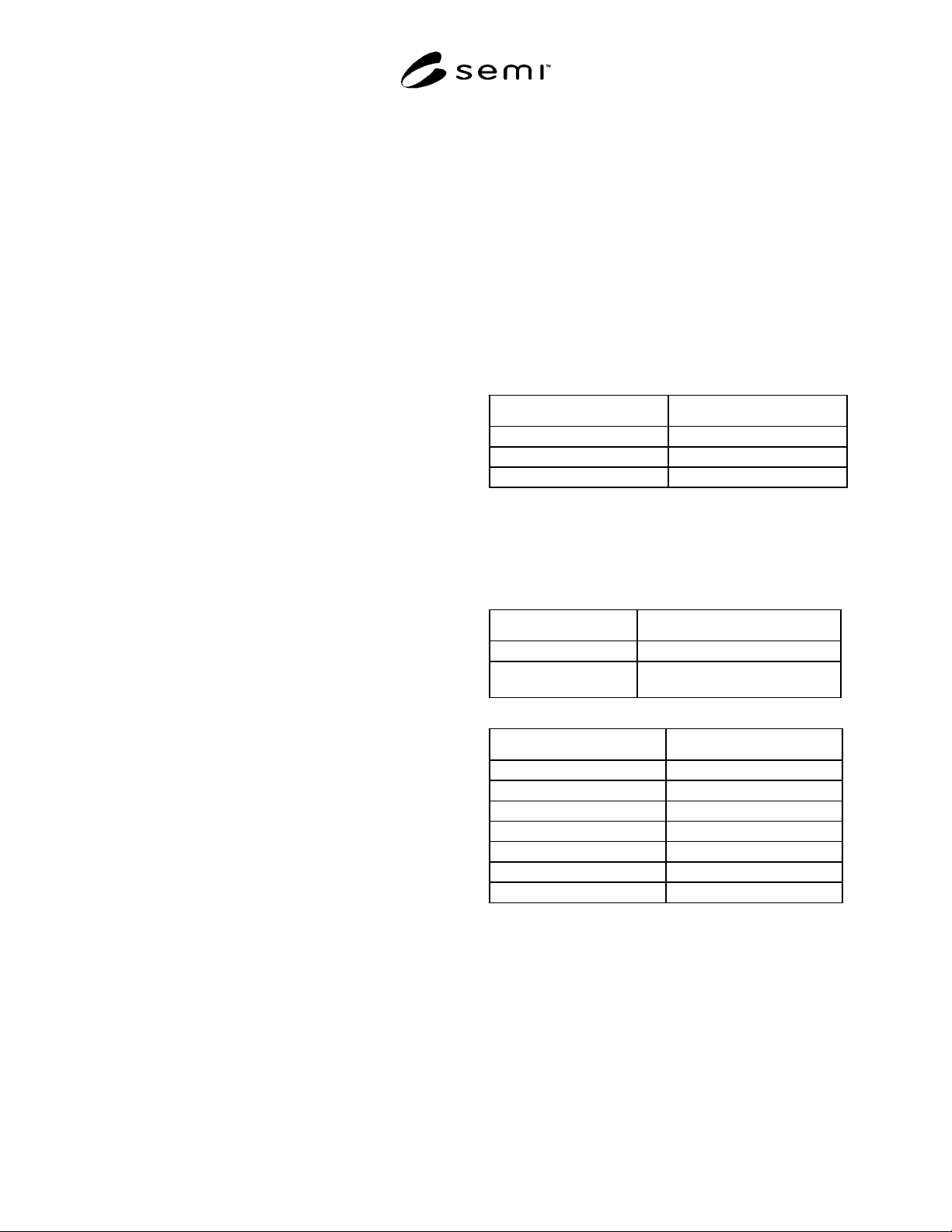
Table 1
Thickness of Metal Strip (mm) Test Load of Vickers Hardness
0.100 to 0.160 1.961 N (200 gf)
over 0.160 to 0.500 4.903 N (500 gf)
over 0.500 9.807 N (1 Kgf)
5.3 Thickness and Width Tolerance
5.3.1 Thickness tolerance for material covered under
this specification shall be chosen from Tables 2 and 3.
Table 2
Thickness Tolerance
0.10 mm to 0.15 mm ± 0.005 mm
over 0.15 mm to 2.0 mm ± 3% of the ordered
material thickness
Table 3
Thickness Tolerance
0.10 mm up to 0.15 mm ± 0.005 mm
0.15 mm up to 0.3 mm ± 0.008 mm
0.3 mm up to 0.5 mm ± 0.010 mm
0.5 mm up to 0.8 mm ± 0.013 mm
0.8 mm up to 1.0 mm ± 0.015 mm
1.0 mm up to 1.5 mm ± 0.020 mm
1.5 mm up to 2.0 mm ±0.025 mm
* Table 3 is used in Europe.
5.3.2 Width tolerance shall be as shown in Tables 4
and 5.
SEMI G4-0302 © SEMI 1982, 2002 3
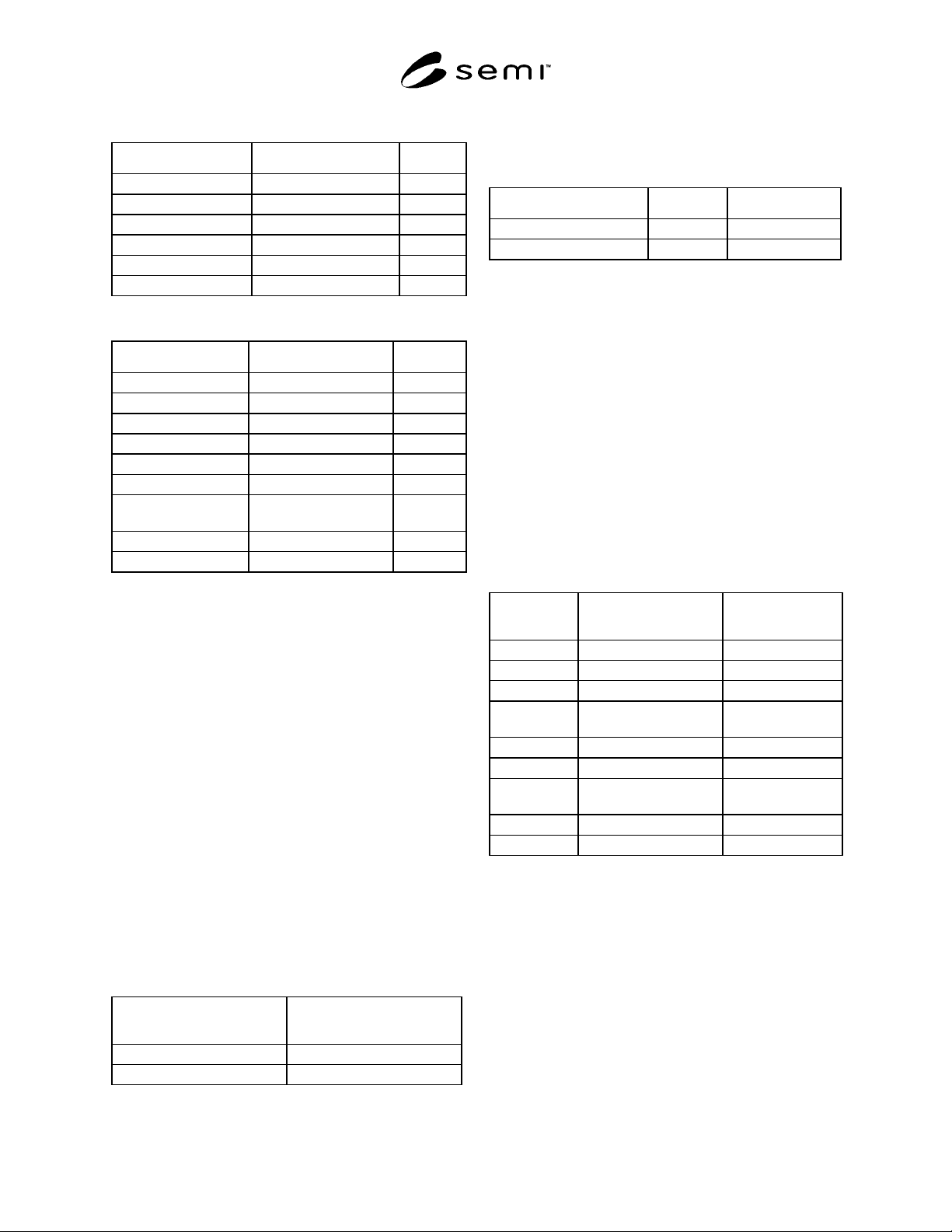
Table 4
Width Thickness Tolerance
under 15 mm to 55 mm 0.1 mm to under 0.3 mm ± 0.05 mm
0.3 mm to under 1.0 mm ± 0.08 mm
1.0 mm to 2.0 mm ± 0.15 mm
over 55 mm to 100 mm 0.1 mm to under 0.3 mm ± 0.08 mm
0.3 mm to under 1.0 mm ± 0.12 mm
1.0 mm to 2.0 mm ± 0.15 mm
Table 5
Width Thickness Tolerance
under 15 mm over 0.1 mm to 0.3 mm ± 0.05 mm
over 0.3 mm to 1.0 mm ± 0.08 mm
over 1.0 mm to 2.0 mm ± 0.15 mm
15 mm to 55 mm over 0.1 mm to 0.3 mm ± 0.05 mm
over 0.3 mm to 1.0 mm ± 0.08 mm
over 1.0 mm to 2.0 mm ± 0.15 mm
Over 55 mm to 100
mm
over 0.1 mm to 0.3 mm ± 0.08 mm
over 0.3 mm to 1.0 mm ± 0.12 mm
over 1.0 mm to 2.0 mm ± 0.15 mm
* Table 5 is used in Europe.
5.4 Surface Finish
5.4.1 The material shall be commercially free of
surface imperfections such as pits, nicks, dents, gouges,
scratches, laminations, or inclusions.
5.4.2 The surface roughness of both sides shall be
measured perpendicular to the direction of rolling and
indicated as the arithmetic average height (R
a
) and the
maximum peak-to-valley roughness height (R
max
).
5.4.2.1 Measurement and designations of surface
roughness shall conform to appropriate area standards
based on country or area of material origin.
5.4.2.1.1 Europe ISO 4287 Part 1
5.4.2.1.2 Japan JIS B0601
5.4.2.1.3 United States ANSI/ASME B46.1
5.4.2.2 Conditions for the measurement are shown in
Table 6.
Table 6
Radius of Diamond
Stylus: Less than 5mm
(Record Actual Size)
Cut Off: 0.8 mm
Stroke: 4 mm
5.4.2.3 Maximum acceptable values for surface
roughness are shown in Table 7.
Table 7
Thickness R
a
R
max
0.1 mm to under 0.3 mm 0.15 µm 1.0 µm (1.5 µm)
0.3 mm to 2 mm 0.20 µm 1.5 µm (2.0 µm)
* Values in parentheses are used in Europe.
5.5 Camber (Edgewise Curvature)
5.5.1 Camber is measured by placing a length of strip
on a flat surface against the edge of a straight edge, as
shown in Figure 1. The straight edge shall be of
sufficient length to equal or exceed the length
traditionally used in the area or country of origin of the
material. The largest amount of separation of the strip
sample from the straight edge shall be measured.
Extreme care must be exercised with this test to ensure
that the sample illustrates a uniform camber (no reverse
curvature should be present in the sample), and also that
it is not bent or kinked, as this could result in a grossly
inaccurate measurement. The maximum camber per
length allowable are shown in Table 8.
Table 8
Width
Thickness
Max camber
allowed in 1 meter
Under 15 mm 0.1 mm to under 0.3 mm 1.8 mm (2.0 mm)
0.3 mm to under 1.0 mm 2.2 mm (2.5 mm)
1.0 mm to 2.0 mm 4.0 mm
15 mm to
55 mm
0.1 mm to under 0.3 mm 1.3 mm
0.3 mm to under 1.0 mm 2.0 mm
1.0 mm to 2.0 mm 3.0 mm
Over 55 mm
to 100 mm
0.1 mm to under 0.3 mm 1.0 mm
0.3 mm to under 1.0 mm 1.5 mm
1.0 mm to 2.0 mm 2.5 mm