semi合集-English.pdf - 第3678页
SEMI PR8-0703 © SEMI 2003 8 7.4.2 EDA Client Configuration — There shall be a persistent equipment con figuration setting for each EDA client that establishes the URL to which equipment-initiated SOAP messages will be se…
SEMI PR8-0703 © SEMI 2003 7
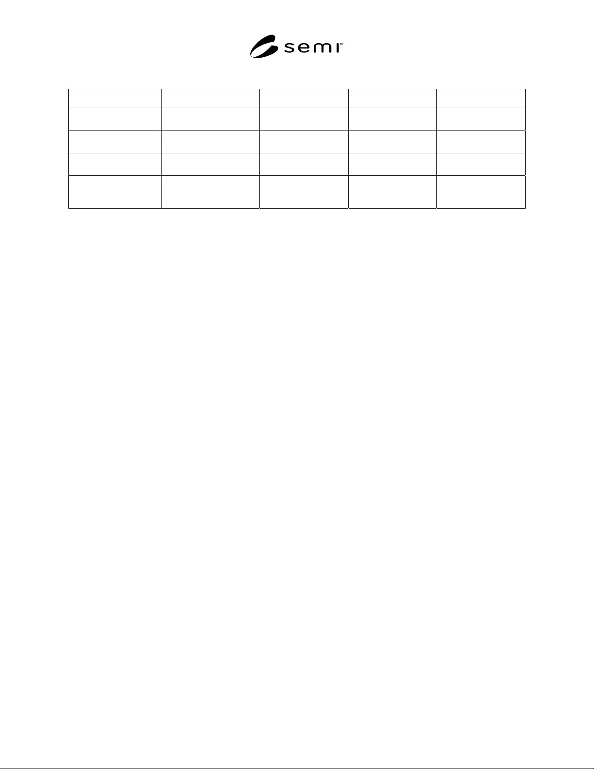
Table 2 MessageHeader XML Definition
Tag Name Description XML Datatype Behavior mustUnderstand
MessageHeader Container element for
From/To/CorrelationId.
complex Required 1
From Identifies the originator of
this message.
anyURI Required n/a
To Identifies the intended
recipient of this message.
anyURI Required n/a
CorrelationId Associates this message
with other messages in the
same message interaction.
string Optional (0 or 1) n/a
7.3.3.1 From Element — This element identifies the sender of a given SOAP message, whether the message is an
event, a request, or a response to a request. It is of XML type anyURI and can be any valid URL or URN. This
specification does not place any restriction on the format used to identify a sender, regardless of whether the sender
is the equipment or an EDA client. All messages originating from the same sender must provide the same value for
the From element so that the recipient may distinguish that sender from others.
7.3.3.1.1 Examples — Some examples of valid From elements are provided as follows:
• <From>urn:equipment-client:icm:utracking-01</From>
• <From>http://myfactory.com/furnace/KF011/EDA</From>
7.3.3.2 To Element — This element identifies the intended recipient of a given SOAP message. It is of XML type
anyURI and can be any valid URL or URN. This specification does not place any restriction on the form (URL or
URN) used to identify a recipient, regardless of whether the recipient is the equipment or an EDA client. All
messages intended for the same recipient must provide the same value for the To element so that the recipient may
distinguish that message from others intended for other recipients. If the message is a response to a request, the
value of the To element in the response must be equal to the value of the From element in the original request
message.
7.3.3.2.1 Examples — Some examples of valid To elements are provided as follows:
• <To>urn:equipment:robofurnace-inc:3JK9UI-02-99UI</To>
• <To>http://factory.icm.com/fdc/app-01</To>
7.3.3.3 CorrelationId Element — If used, the value of this element in the initial request message should be unique
for that client. Each request shall have a different CorrelationId value. For messages that are replies, the value shall
be equal to the value of the CorrelationId element provided in the original request message.
7.3.3.3.1 Examples — some examples of valid CorrelationId elements are provided as follows:
• <CorrelationId>5a389ad2-22dd-11d1-aa77-002035b29092</CorrelationId>
• <CorrelationId>4776</CorrelationId>
7.4 Equipment Configuration
7.4.1 Data Management Configuration — There shall be a persistent equipment configuration setting that controls
whether data management (see Section 7.6) is performed via SECS/GEM or via SOAP. The implementation and
behavior of this configuration setting is to be defined by the supplier, but shall not be implemented in such a way
that it is possible to perform data management via both SOAP and SECS/GEM concurrently. When the equipment
is configured to accept data management messages via SOAP, the equipment shall not accept these messages via
SECS/GEM. Likewise, when the equipment is configured to accept data management messages via SECS/GEM,
the equipment shall not accept these messages via SOAP. It must be possible for the factory to change this
configuration setting without requiring the involvement of the supplier.
SEMI PR8-0703 © SEMI 2003 8
7.4.2 EDA Client Configuration — There shall be a
persistent equipment configuration setting for each
EDA client that establishes the URL to which
equipment-initiated SOAP messages will be sent for
that client, and the value of the ‘From’ element of the
‘MessageHeader’ SOAP header that that client will use
in all client-initiated SOAP messages to the equipment.
If an EDA client will be performing data management
via SECS/GEM, it is not necessary to configure the
value of the ‘From’ element of the ‘MessageHeader’
SOAP header for that client, but the configuration must
indicate that the client can perform data management
via SECS/GEM. It must be possible for the factory to
change these configuration settings without requiring
the involvement of the supplier.
7.4.3 Equipment Identity Configuration — There shall
be a persistent equipment configuration setting that
establishes the value of the ‘From’ element of the
‘MessageHeader’ SOAP header that will be used for all
SOAP messages sent by the equipment. It must be
possible for the factory to change this configuration
setting without requiring the involvement of the
supplier.
7.4.4 Multi-Client Considerations — When the data
management interface configuration setting is set to
SECS/GEM, the equipment shall accept data
management messages only from the single configured
SECS/GEM client, and shall send all equipment-
initiated SOAP messages only to the single URL that
was configured for that client. When the data
management configuration setting is set to SOAP, the
EDA interface may be multi-client, if the equipment
supports this optional feature, and shall accept data
management messages from any valid configured EDA
SOAP client.
7.5 EDA State Models
7.5.1 EDA Communications State Diagram
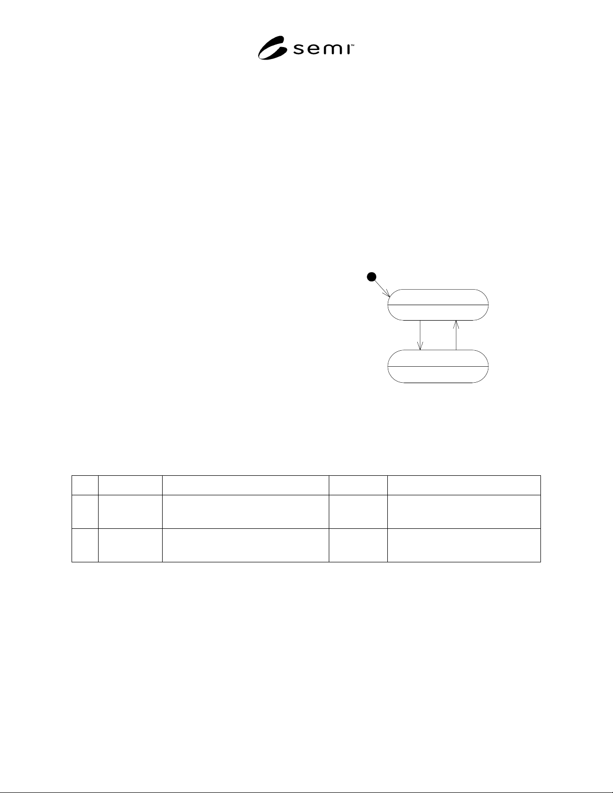
7.5.1.1 Figure 4 shows the state model for the
availability of the EDA interface to the factory. When
disabled, the equipment is not in a condition whereby it
can process data management messages, nor transmit
data to clients. When enabled, the equipment can both
process EDA data management messages, as well as
transmit data to clients.
EDADisabled
EDAEnabled
1 2
H
Figure 4
EDA Communications State Diagram
7.5.2 EDA Communications Transition Definition Table
Table 3 EDA Communications Transition Definition Table
Num Previous State Trigger New State Actions
1 EDADisabled Equipment powers up, achieves condition to
accept EDA data management requests and
transmit DCP data.
EDAEnabled For each configured client, equipment
begins sending EdaEnabled message, as
described in Section 7.7.4.1.
2 EDAEnabled Equipment is entering a state wherein it will
not be possible to perform EDA activities.
EDADisabled For each configured client, equipment
sends EdaDisabled message, as described
in Section 7.7.4.2.
7.5.3 Data Collection Plan State Diagram
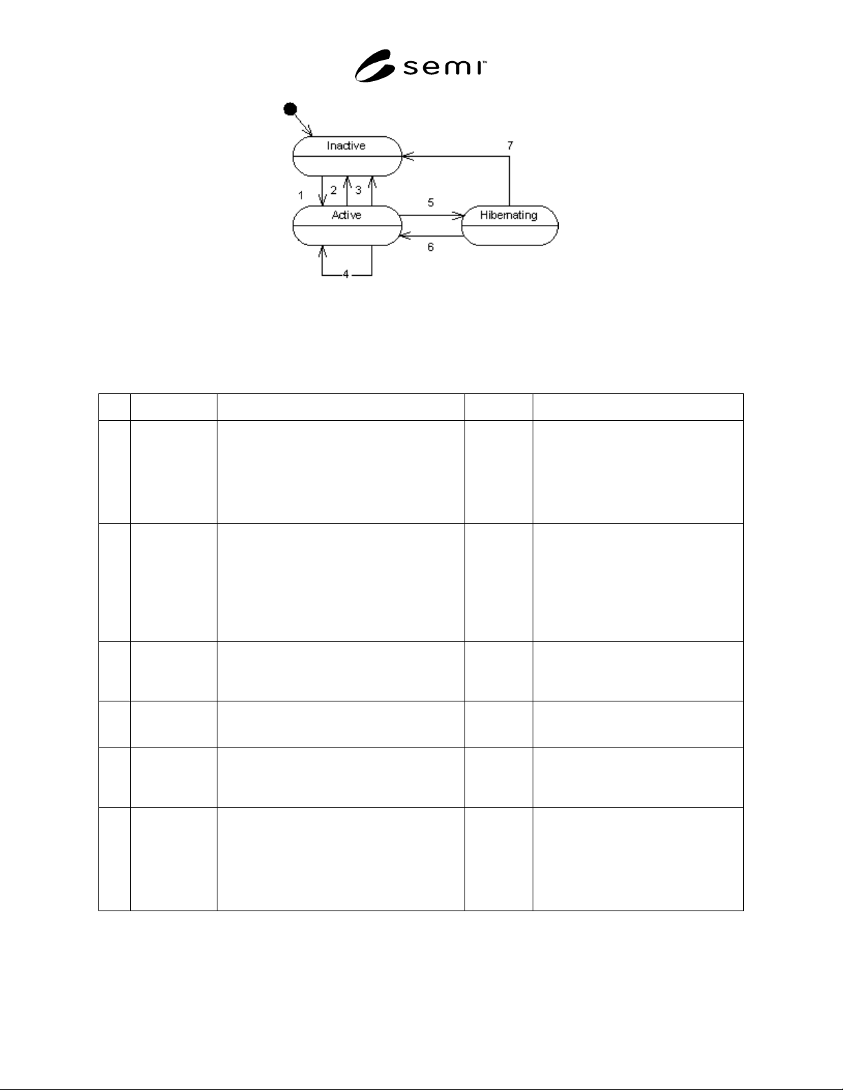
7.5.3.1 Figure 5 shows the EDA client’s view of equipment behavior for each DCP defined on the equipment. Each
DCP for a given client follows this behavior model independently of every other DCP on the equipment. For
example, if client A activates “DCP1”, and client B does not, and client A subsequently requests the list of active
DCP’s from the equipment, “DCP1” will be returned in the list of active plans, because it is in the “Active” state for
client A. If client B requests a list of active DCP’s from the equipment, “DCP1” will not be returned in the list of
active plans, because client B did not activate “DCP1”, and it is still in the “Inactive” state for client B.
SEMI PR8-0703 © SEMI 2003 9
Figure 5
Data Collection Plan State Diagram
7.5.4 Data Collection Plan Transition Definition
Table 4 Data Collection Plan Transition Definition Table
Num Previous State Trigger New State Actions
1 Inactive A client requests the activation of a DCP using a
valid DCP id, via the ActivatePlan operation
Active The equipment responds affirmatively to
the request, and begins sending the data
included in the plan to the client. If
activated with “UntilDeactivated” set to
“true”, the equipment shall store a record
in non-volatile memory of the DCP ID
and its client’s address information.
2 Active A client requests the deactivation of a DCP
using a valid DCP id via the DeactivatePlan
operation.
Inactive The equipment responds affirmatively to
the request, and discontinues sending
data defined by that DCP to the client. If
the DCP had been activated with
“UntilDeactivated” set to “true”, the
equipment shall remove the previously
stored record regarding the DCP and its
client from non-volatile memory.
3 Active The equipment is entering a state in which it will
not be possible to transmit data to its client. The
DCP was activated with “UntilDeactivated” set
to “false” (see Section 7.6.2.4.1).
Inactive The equipment shall cease sending data
included in the DCP to the client.
4 Active A client requests the activation of the DCP, via
the ActivatePlan operation. The DCP is already
active.
Active The equipment responds with an error,
indicating that the DCP is already active.
5 Active The equipment is entering a state in which it will
not be possible to transmit data to its client. The
DCP was activated with “UntilDeactivated” set
to “true” (see Section 7.6.2.4.1)
Hibernating The equipment shall cease sending data
included in the DCP to the client.
6 Hibernating The equipment is entering a state in which it will
be possible to transmit data to its client. The
DCP was activated with “UntilDeactivated” set
to “true” (see Section 7.6.2.4.1). The client has
responded to the EdaEnabled message within the
configured number of attempts (see Section
7.7.6.1).
Active The equipment shall begin sending the
data included in the DCP to the client
that originally activated it, as specified in
the record that was stored in non-volatile
memory for the DCP when it was
activated.