semi合集-English.pdf - 第738页
SEMI E100-1104 © SEMI 2000, 2004 1 SEMI E100-1104 SPECIFICATION FOR A RETI CLE SMIF POD (RSP) USED TO TRANSPORT AND STORE 6 INCH OR 230 mm RETICLES This specificatio n was technically approved b y the Global Physical Int…
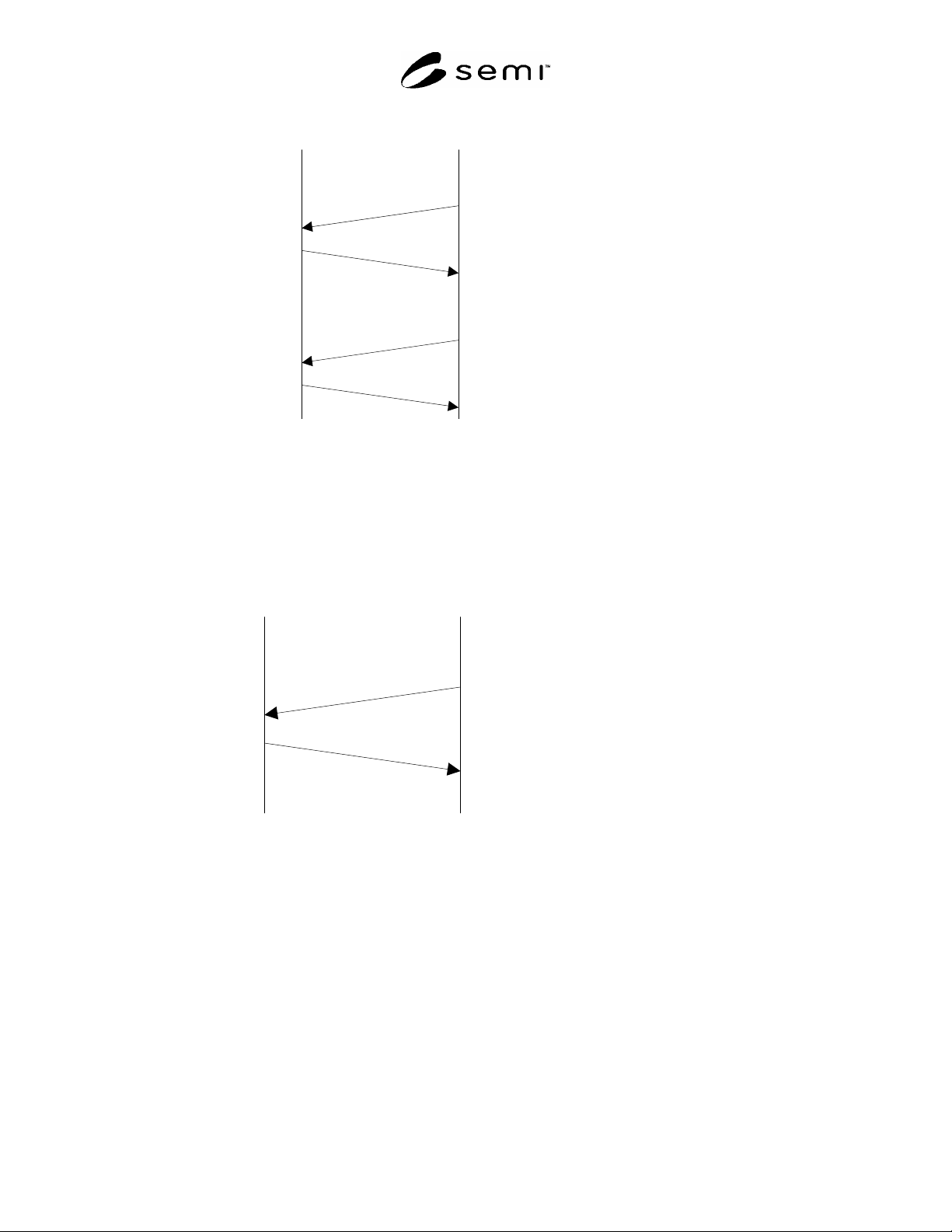
SEMI E99.1-1104 © SEMI 2000, 2004 6
CIDRW
Upstream
Controller
S18,F13 Subsystem
Command Request
Target ID = “00”
CPVAL = “OP”, “MT”
S18,F14 Subsystem
Command Acknowledge
SSACK = “NO”
S18,F11 Write ID
Target ID = “01”
MID = “ABC”
S18,F12 Write ID Data
SSACK = “NO”
Figure R1-3
Write ID Data Scenario
R1-4 Write Data
R1-4.1 The upstream controller sends a Write Data Request message to the CIDRW for Head 1 and DataSeg 1.
The CIDRW Head 1 writes the data, and the CIDRW returns the results to the upstream controller.
CIDRW
Upstream
Controller
S18,F7 Write Data Request
Target ID = “01”
DataSeg = “0”
Data = “xxxxxxx”
S18,F8 Write Data
Acknowledge
SSACK = “NO”
Figure R1-4
Write Data Scenario
NOTICE: SEMI makes no warranties or representations as to the suitability of the standard set forth herein for any
particular application. The determination of the suitability of the standard is solely the responsibility of the user.
Users are cautioned to refer to manufacturer’s instructions, product labels, product data sheets, and other relevant
literature respecting any materials mentioned herein. These standards are subject to change without notice.
The user’s attention is called to the possibility that compliance with this standard may require use of copyrighted
material or of an invention covered by patent rights. By publication of this standard, SEMI takes no position
respecting the validity of any patent rights or copyrights asserted in connection with any item mentioned in this
standard. Users of this standard are expressly advised that determination of any such patent rights or copyrights, and
the risk of infringement of such rights, are entirely their own responsibility.
Copyright by SEMI® (Semiconductor Equipment and Materials
International), 3081 Zanker Road, San Jose, CA 95134. Reproduction of
the contents in whole or in part is forbidden without express written
consent of SEMI.

SEMI E100-1104 © SEMI 2000, 2004 1
SEMI E100-1104
SPECIFICATION FOR A RETICLE SMIF POD (RSP) USED TO
TRANSPORT AND STORE 6 INCH OR 230 mm RETICLES
This specification was technically approved by the Global Physical Interfaces and Carriers Committee and is
the direct responsibility of the North American Physical Interfaces and Carriers Committee. Current edition
approved by the North American Regional Standards Committee on August 16, 2004. Initially available at
www.semi.org September 2004; to be published November 2004. Originally published February 2000,
previously published March 2002.
1 Purpose
1.1 This standard specifies the Reticle SMIF Pod
(RSP) used to transport and store 6 inch or 230 mm
reticles in a reticle (photomask) or integrated circuit
(IC) manufacturing facility.
2 Scope
2.1 This standard is intended to set an appropriate level
of specification that places minimal limits on
innovation while ensuring modularity and inter-
changeability at all mechanical interfaces. Most of the
requirements given in this specification are in the form
of maximum or minimum dimensions with very few
required surfaces. Only the physical interfaces for the
RSP are specified; no materials requirements or micro-
contamination limits are given in this specification.
2.2 The pellicle exclusion volumes of this specification
accommodate pellicles which extend the full length of
the reticles. The pellicle exclusion volume widths are
limited to 151 mm for 230 mm reticles, and 129 mm for
6 inch reticles.
2.3 The RSP has the following components, sub-
components, and other features. A “” symbol indicates
components or features which are required and a “”
symbol indicates components or features which are
optional.
Top
robotic handling flange (optional)
Interior
supports for one 6 inch or 230 mm reticle
reticle capture mechanism
end-effector exclusion volume
2 safety rail exclusion volumes
pellicle exclusion volume
transverse pellicle exclusion volume
Sides
2 side handling flanges on the sides parallel to
the bi-lateral reference plane (optional)
1 carrier ID exclusion volume on the rear side
2 side handling exclusion volumes
Bottom
door compatible with SMIF as defined in
SEMI E19.4
pod latch-pin holes
features which mate with kinematic coupling
pins
carrier sensing pads as defined in SEMI E1.9
4 info pads
4 bottom conveyor rails
NOTICE: This standard does not purport to address
safety issues, if any, associated with its use. It is the
responsibility of the users of this standard to establish
appropriate safety and health practices and determine
the applicability of regulatory or other limitations prior
to use.
3 Referenced Standards
3.1 SEMI Standards
SEMI E1.9 — Mechanical Specification for Cassettes
Used to Transport and Store 300 mm Wafers
SEMI E19.4 — 200 mm Standard Mechanical Interface
(SMIF)
SEMI E30.1 — Inspection and Review Specific
Equipment Model (ISEM)
SEMI E47.1 — Provisional Mechanical Specification
for Boxes and Pods Used to Transport and Store 300
mm Wafers
SEMI E57 — Mechanical Specification for Kinematic
Couplings Used to Align and Support 300 mm Wafer
Carriers
SEMI P5 — Specification for Pellicles

SEMI E100-1104 © SEMI 2000, 2003 2
NOTICE: Unless otherwise indicated, all documents
cited shall be the latest published versions.
4 Terminology
4.1 Definitions
4.1.1 bilateral reference plane — a vertical plane that
bisects the reticle and is perpendicular to both the
horizontal and facial reference planes. The bilateral
reference plane is coplanar with the bilateral datum
plane defined in SEMI E57.
4.1.2 facial reference plane — a vertical plane which
bisects the reticle and is parallel to the front side of the
pod (where reticles are removed or inserted). The facial
reference plane passes through the center of the
200 mm SMIF as defined in SEMI E19.4. The facial
reference plane is coplanar with the facial datum plane
defined in SEMI E57.
4.1.3 horizontal reference plane — a horizontal plane
coplanar with the top surface of the port door as defined
in SEMI E19.4. The horizontal reference plane is
coplanar with the horizontal datum plane defined in
SEMI E57.
4.1.4 minienvironment — a localized environment
created by an enclosure to isolate the product from
contamination and people.
4.1.5 nominal reticle center line — the line that is
defined by the intersection of the two vertical reference
planes (facial and bilateral) and passes through the
nominal center of the seated reticle (which must be
horizontal when the carrier is placed on the SMIF as
defined in SEMI E19.4).
4.1.6 pellicle — as defined in SEMI P5.
4.1.7 reticle — as defined in SEMI E30.1.
4.1.8 Reticle SMIF Pod (RSP) — a minienvironment
compatible carrier capable of holding one 6 inch or one
230 mm reticle in a horizontal orientation during
transport and storage and is compatible with a Standard
Mechanical Interface (SMIF) per SEMI E19.4.
4.1.9 robotic handling flanges — horizontal
projections on the top of the box for lifting and rotating
the box (as defined in SEMI E47.1).
4.1.10 side handling flanges — horizontal projections
on the sides of the pod (sides parallel to the bilateral
reference plane) for manual or automated lifting,
transportation or positioning of the pod.
5 Ordering Information
5.1 Intended Use — This standard is intended to
specify reticle carriers over a reasonable lifetime of use,
not just those in new condition. For this reason, the
purchaser needs to specify a time period and the
number and type of uses to which the carriers will be
put. It is under these conditions that the carriers must
remain in compliance with the requirements listed in
Section 6.
5.2 Reticle Size and Thickness — The purchaser needs
to specify the reticle size and thickness to be
accommodated in the RSP.
5.3 Optional Features — The purchaser needs to
specify whether optional components (identified in
Section 2) are required.
5.4 Temperature Ranges — The purchaser needs to
specify two sets of temperatures to which the RSPs
might be exposed. An operating temperature range is
the set of environmental temperatures in which the
RSPs will remain in compliance with the requirements
listed in Section 6. A temporary temperature range is
the set of environmental temperatures to which the pods
can be exposed such that when the RSPs return to the
operating temperature range, the RSPs will be in
compliance with the requirements listed in Section 6.
Limits on exposure times to elevated temperatures
should be specified.
5.5 Electrostatic Dissipation — The end user may
require a continuous path to ground from the reticle to
the carrier registration and handling features. The
purchaser needs to specify whether electrostatic
dissipation is required.
5.6 Contamination Requirements — The purchaser
needs to specify their contamination requirements.
6 Requirements
6.1 Symmetry — Most of the dimensions of the RSP
are determined with respect to the three orthogonal
reference planes defined in this document: the facial
reference plane, the horizontal reference plane and the
bilateral reference plane. All dimensions are symmetric
about the bilateral reference plane except the latch
features. All dimensions are symmetric about the facial
reference plane except the registration features, carrier
sensing pads, info pads, and latch features.
6.2 Door — The pod door, and its frame on the bottom
of the pod, must be compatible with a port which
conforms to SEMI E19.4.
6.3 Reticle Centering and Capture — When the carrier
is closed, the reticle must be secured in all degrees of
freedom within the carrier to prevent movement during
transport and must be centered with respect to the SMIF
defined in SEMI E19.4. A bisecting plane through the
reticle, parallel to the bilateral reference plane must be
within x114 of the bilateral reference plane of the load
port when the reticle is seated in the carrier. A