semi合集-English.pdf - 第4484页
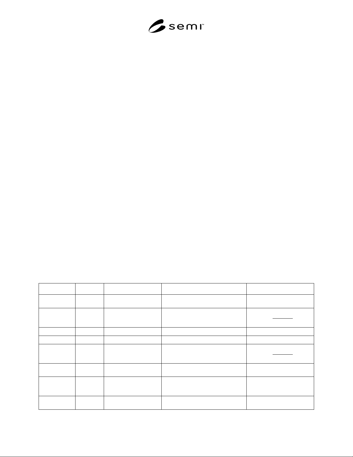
SEMI D18-0299 E © SEMI 19 99, 2001 5 Symbol Us ed Shown in Datum Me asured From Boundary or Feature Me asured To: Algebraic Re lation or Value x 8 Figure 3 bilateral datum plane inside edge of cassette sensing pad areas …
SEMI D18-0299
E
© SEMI 1999, 2001 4
above the top substrate). Table 1 defines the dimensions
shown in this and following figures.
6.7 Cassette Top — The boundaries of the cassette top
domain contain any part of the cassette higher than z9
above the top substrate.
6.8 Cassette Bottom — Figure 3 shows a bottom view
of the boundaries of the cassette bottom domain (which
contains any part of the cassette lower than z4 above the
horizontal datum plane). When the cassette is fully
down, the cassette placement sensing pads must be z2
above the horizontal datum plane.
6.9 Vertical Dimensions — Figure 4 shows the
vertical dimensions of the left half of the cassette as
viewed from the rear. Note that z5 (the height of the
bottom nominal substrate seating plane above the
horizontal datum plane) and z8 (the distance between
adjacent nominal substrate seating planes) are given as
reference dimensions with no tolerance. This means
that the sum of actual height variations in the cassette
from the horizontal datum plane to the mizo tooth or
slot holding each substrate must be contained within the
tolerance of z6 with no further stack-up at each higher
substrate.
6.9.1 The open space for the substrate extraction
volume is indicated by dimensions x6 and y7 and is
symmetric about the bilateral and facial datum planes,
respectively. The top of the extraction volume is z7
above the nominal substrate seating plane and its
bottom is half of the minimum z7 dimension above the
nominal substrate seating plane. The cassette must give
extra horizontal clearance once the substrate is picked
up from wherever it ends up (within the bounds of the
substrate pick-up volume) after transport in the cassette.
6.9.2 The open space for the substrate set-down
volume is indicated by dimensions x5 and y6 and is
symmetric about the bilateral and facial datum planes,
respectively. The top of this volume is half of z7 above
the nominal substrate seating plane and its bottom is z6
above the nominal substrate seating plane. The
substrate should be placed within the bounds of the
substrate set-down volume to avoid touching the edge
of the substrate to the side of the cassette.
6.9.3 The substrate pick-up volume is defined by an
area indicated by dimensions x5 and y5 and is
symmetric about the bilateral and facial datum planes,
respectively. Its top and bottom are the upper and
lower tolerance of z6 around the nominal substrate
seating plane. If a substrate is placed in the substrate
set-down volume and is then pushed to the rear of the
cassette, then the entire bottom of the substrate must be
contained in the substrate pick-up volume.
6.10 Pitch and Capacity — Table 2 shows the
different options with regard to the substrate pitch
(spacing) and the cassette capacity.
6.11 Inner and Outer Radii — All concave features
may have as much as a 1 mm (0.04 in.) radius to allow
for cleaning and to prevent contaminant build-up. All
required convex features (such as the robotic handling
flanges, and the corners of the cassette top and bottom
domains) must also have a minimum radius of 1 mm
(0.04 in.) to prevent small contact patches with large
stresses that might cause wear and particles.
Table 1 Cassette Side Domains
Symbol Used Shown in Datum Measured From Boundary or Feature Measured To: Algebraic Relation or Value
r1 Figure 3 center of coupling
exclusion zone
outside edge of coupling exclusion
zone
<15
x1 Figure 2 bilateral datum plane encroachment of cassette side
domains on substrate extraction
volume
2
57.0×
≥
W
x2 Figures 2 bilateral datum plane outside edge of cassette side domains
371 +≤ W
x3 Figures 2 bilateral datum plane inside edge of rear cassette domains
401 −≥ x
x4 Figures 2 bilateral datum plane outside edge of rear cassette domains
2
57.0×
≥
W
x5Figures 2
and 4
nominal substrate
center line
outside edge of substrate pick-up
volume
21 +≥ W
x6Figures 2
and 4
nominal substrate
center line
encroachment of cassette side
domains on substrate extraction
volume
5x≥
x7 Figures 2 nominal substrate
center line
outside edge of cassette top and
bottom domain
37+
1W≤
SEMI D18-0299
E
© SEMI 1999, 20015
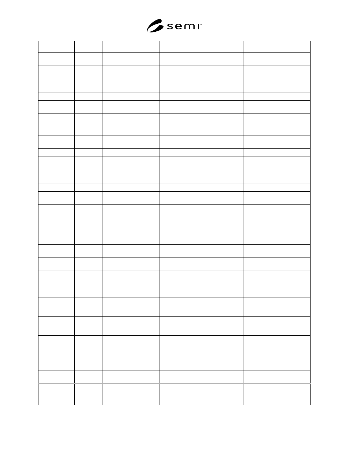
Symbol Used Shown in Datum Measured From Boundary or Feature Measured To: Algebraic Relation or Value
x8 Figure 3 bilateral datum plane inside edge of cassette sensing pad
areas
0.711 ×= W ±5.0
x9 Figure 3 bilateral datum plane outside edge of cassette sensing pad
areas
.7801 ×= W ±5.0
x10 Figure 4 bilateral datum plane encroachment of cassette top domain
on robotic handling flange space
1.02
1 ×≤ W
x11 Figure 4 bilateral datum plane far side of robotic handling flanges
1.051 ×≤ W
x12 Figures 3 bilateral datum plane inside edge of conveyor rail
exclusion zones
0.752
1 ×≥ W
x13 Figures 3 bilateral datum plane outside edge of conveyor rail
exclusion zones
0.877 1 ×≤ W
x14 Figure 3 bilateral datum plane center of coupling exclusion zones
0.9455 1 ×= W ± 0.1
x15 Figures 3
and 6
bilateral datum plane centerline of V-rail roller
0.815 1 ×= W ± 0.2
x16 Figure 6 bilateral datum plane centerline of float roller
19x=± 2.0
x17 Figure 3 bilateral datum plane inside edge of facial datum plane V-
groove
0.0245 1 ×= W ± 0.2
x18 Figure 3 bilateral datum plane outside edge of facial datum plane
V-groove
0.020
1 ×= W ± 0.2
x19 Figure 6 bilateral datum plane left edge of V-groove exclusion zone
0.069 1 ×≥ W
x20 Figure 6 bilateral datum plane right edge of V-groove exclusion
zone
0.109
1 ×≥ W
x21 Figure 6 bilateral datum plane inside edge of float roller exclusion
zone
0.742 1 ×≤ W
x22 Figure 6 bilateral datum plane outside edge of float roller exclusion
zone
0.884 1 ×≥ W
y1 Figure 2 facial datum plane encroachment of cassette side
domain
031.0
1 ×≥ L
y2 Figure 2 facial datum plane encroachment of cassette side
domain
454.01 ×≤ L
y3 Figure 2 facial datum plane encroachment of cassette side
domain
515.01 ×≥ L
y4 Figure 2 facial datum plane encroachment of cassette side
domain
938.0
1 ×≤ L
y5 Figure 2 facial datum plane outside edge of substrate pick-up
volume
11 +≤
L
y6 Figure 2 facial datum plane encroachment of cassette side
domains on substrate set-down
volume
11 +≥
L
y7 Figure 2 facial datum plane encroachment of cassette side
domains on substrate extraction
volume
31 +≥ L
y8 Figure 2 facial datum plane boundary of rear cassette domain
12.11 ×≤ L
y9 Figures 2 facial datum plane outside edge of cassette top and
bottom plate domain
21.1
1 ×≤ L
y10 Figures 3 facial datum plane inside edge of cassette top and
bottom plate indent
985.01 ×≤ L
y11 Figure 3 facial datum plane inside edge of cassette sensing pad
areas
708.01 ×≥ L
y12 Figure 3 facial datum plane outside edge of cassette sensing pad
areas
954.01 ×≤ L
y13 Figure 3 facial datum plane center of coupling exclusion zones
923.01 ×= L ± 0.1
SEMI D18-0299
E
© SEMI 1999, 2001 6
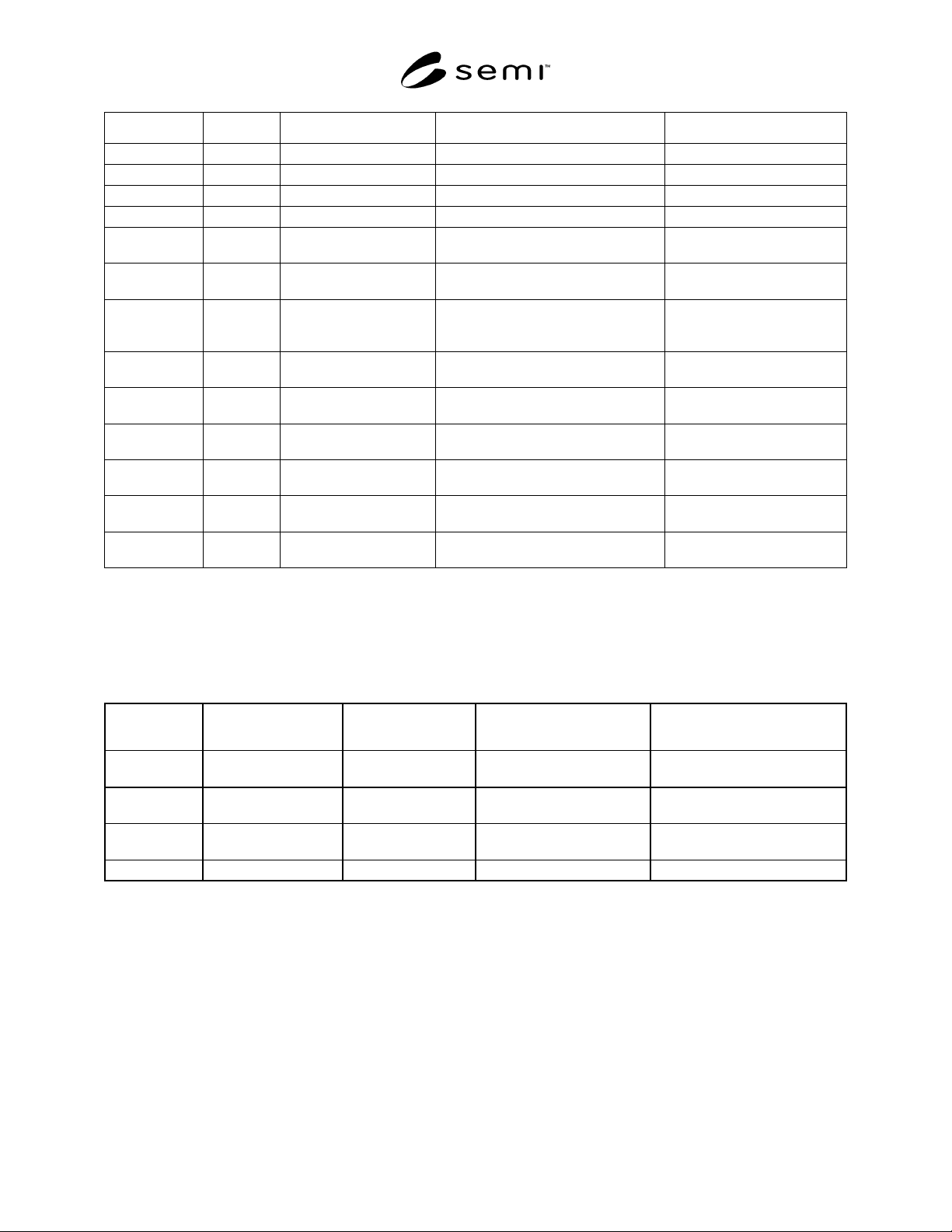
Symbol Used Shown in Datum Measured From Boundary or Feature Measured To: Algebraic Relation or Value
z1 Figure 4 horizontal datum plane bottom of cassette bottom domain
≥ 2
z2 Figure 4 horizontal datum plane bottom of cassette sensing pads
=3 ± 0.5
z3 Figure 6 horizontal datum plane bottom surface of conveying surface
=2 ± 0.5
z4 Figure 4 horizontal datum plane top of cassette bottom domain
≤ 40
z5 Figure 4 horizontal datum plane bottom nominal substrate seating
plane
= 60
z6 Figure 4 each nominal substrate
seating plane
bottom of substrate
= ± 0.5
z7 Figure 4 each nominal substrate
seating plane
encroachment of cassette side
domains on clearance above the
substrate
See Table 2.
z8 Figure 4 each nominal substrate
seating plane
adjacent nominal substrate seating
planes
See Table 2.
z9 Figure 4 top nominal substrate
seating plane
bottom of cassette top domain
≥ z7 + 1
z10 Figure 4 top nominal substrate
seating plane
bottom of clearance under robotic
handling flange
≤ 30
z11 Figure 4 top nominal substrate
seating plane
top of clearance under robotic
handling flange
= 40 ± 1
z12 Figure 4 top nominal substrate
seating plane
top of top cassette domain
≤ 50
z14 Figure 6 Horizontal Datum Plane top of V-rail, V-groove, and float
roller exclusion zones
= 24.86 ± 0.12
W= the length in millimeters of the substrate edge perpendicular to the bilateral datum plane.
W
1
= one half the length of W
L= the length in millimeters of the substrate edge perpendicular to the facial datum plane.
L
1
= one half the length of L
All values in millimeter (mm)
Table 2 Pitch and Capacity Options
Substrate Size Cassette Capacity (c) Substrate Pitch (z8) Substrate Clearance (z7) Resulting Cassette Height
(z5-z1)+((z8*(c-1))+z12
550 mm x
650 mm
25 substrates 20 mm (0.79 in.) 16 mm (0.63 in.) minimum 580 mm (22.83 in.) maximum
600 mm x
720 mm
25 substrates 20 mm (0.79 in.) 16 mm (0.63 in.) minimum 580 mm (22.83 in.) maximum
960 mm x
1100 mm
20 30 mm (1.18 in.) 20 mm (0.79 in.) 678 mm (26.7 in.) maximum
4 not yet defined