semi合集-English.pdf - 第2299页
SEMI E81-0600 © 1999, 2 000 36 B < < In te r f a c e > > C < <I nt erf ac e> > A <<I n terface >> A s s oc i at i o n C las s D << In te r fa c e > > 2 0. . 1 2 0. . 1 As s…
SEMI E81-0600 © 1999, 200035
7.3.4.11.2 In general, each task specification is a
definition of a business process and a task workflow to
carry out that business process. There is a diversity of
information that could appear in a business process,
including associated operational business rules and
constraints, workflow traversal logic, and data
structures for tasks, recipes, steps, etc. There is not
industry consensus on representing these generic task
specification details. For each specific job type, the
CIM Framework defines some specification structure,
but leaves room for suppliers and users to define
additional data and behavior and to leverage workflow
engines and evolving workflow standards [Workflow,
WfMC].
7.4 Specification Conventions
7.4.1 This section provides an overview of the
notations required to express the CIM Framework
specifications. These notations provide the
representational formalisms for all CIM Framework
specifications. This section is a reference rather than a
tutorial. Hence, those unfamiliar with these topics are
strongly encouraged to consult the materials listed in
the references for a more thorough explanation.
7.4.2 CIM systems requirements and the architectural
principles upon which the CIM Framework was
founded were derived through use of industry
standards, practices reported in the literature, and other
state-of-the-art information. The requirements of the
CIM Framework are specified using a combination of
graphical and textual notations. Where applicable,
methods were employed and notations applied that were
supported by the automation of computer-aided
software engineering tools.
7.4.3 Model Specification and Graphical Notation
Usage
7.4.3.1 This section briefly describes the graphical
notations used to specify the semantics of the
framework, including the following:
• Component Relationship Model.
• Component Information Model.
• Component Interaction Diagram.
• State Model.
7.4.3.2 Component Relationship Model
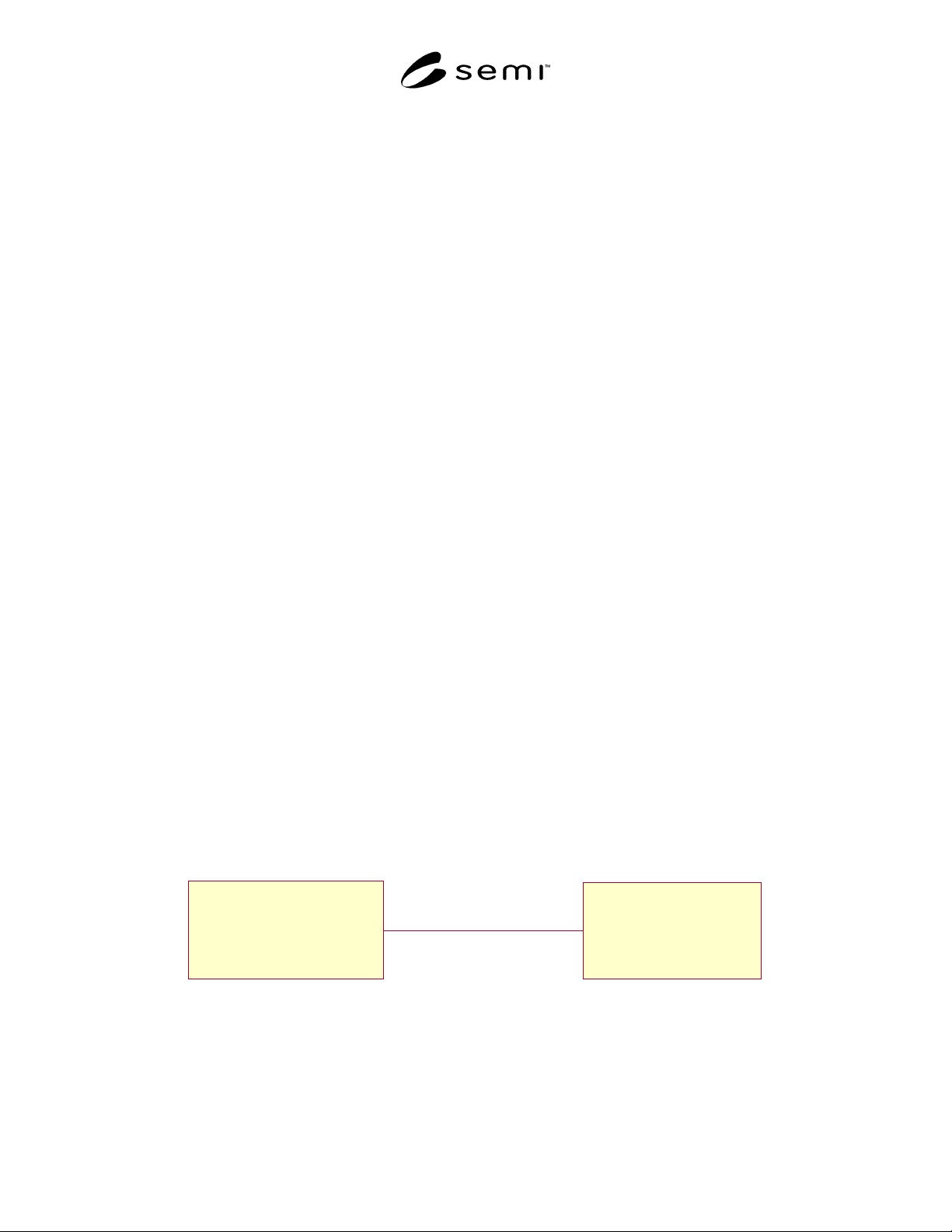
7.4.3.2.1 The Component Relationship Model was
developed specifically for the framework specification
as a mechanism to show relationships among
framework components. It shows the logical
combination of components and the relationships
among the component parts. Figure 22 depicts the
Component Relationship Model.
7.4.3.2.2 This model is based on the Unified Modeling
Language (UML) Class Diagram [UML] with added
stereotypes to represent the components. The UML
Association concept is abstracted to represent the high-
level relationships between components of the
framework.
7.4.3.3 Component Information Model
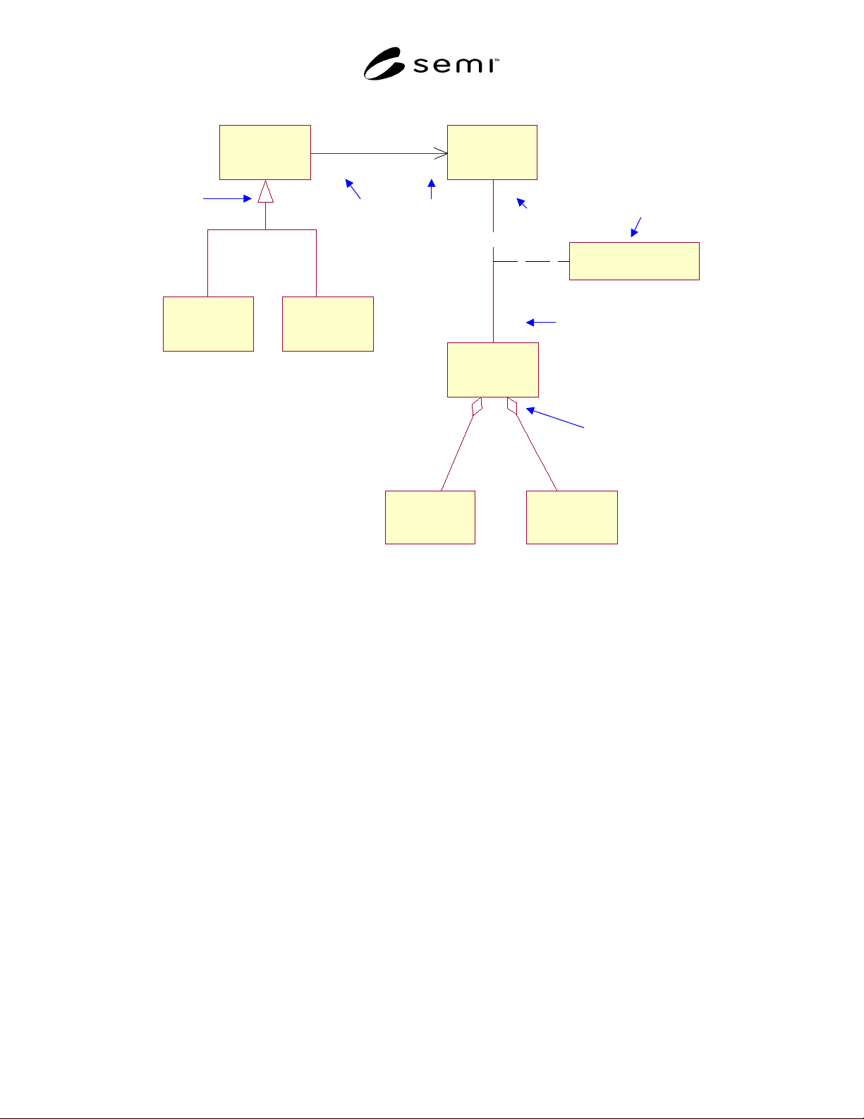
7.4.3.3.1 The Component Information Model shows
the specified CIM Framework interfaces along with the
relationships between those interfaces. This model is
based on the UML Class Diagram [UML] with the
stereotype «Interface» to indicate that the classes are
interfaces rather than implementation artifacts. This
model shows generalization as applied to interface
inheritance, aggregation of interfaces, and the use of an
Association Class to represent data associated with an
association between two interfaces. The associations
also capture specific semantics of the relationship,
including multiplicity and optionality as shown in
Figure 23.
B
<<Component>>
A
<<Component>>
Association
Figure 22
Component Relationship Model
SEMI E81-0600 © 1999, 2000 36
B
<<In te r fa c e >>
C
<<Interface>>
A
<<Interface>>
Association Class
D
<<Interface >>
2
0..1
2
0..1
Association Nam e
F
<<Interface>>
E
<<Interface >>
1..*
1
1..*
1
Association Name
G
<<Interface>>
Zero or
One
Subtype
Relationship
Part-Whole
Relationshop
Data-
Carrying
RelationshipExactly
Two
One
One or
Many
Figure 23
Information Model Example
7.4.3.4 Component Interaction Model
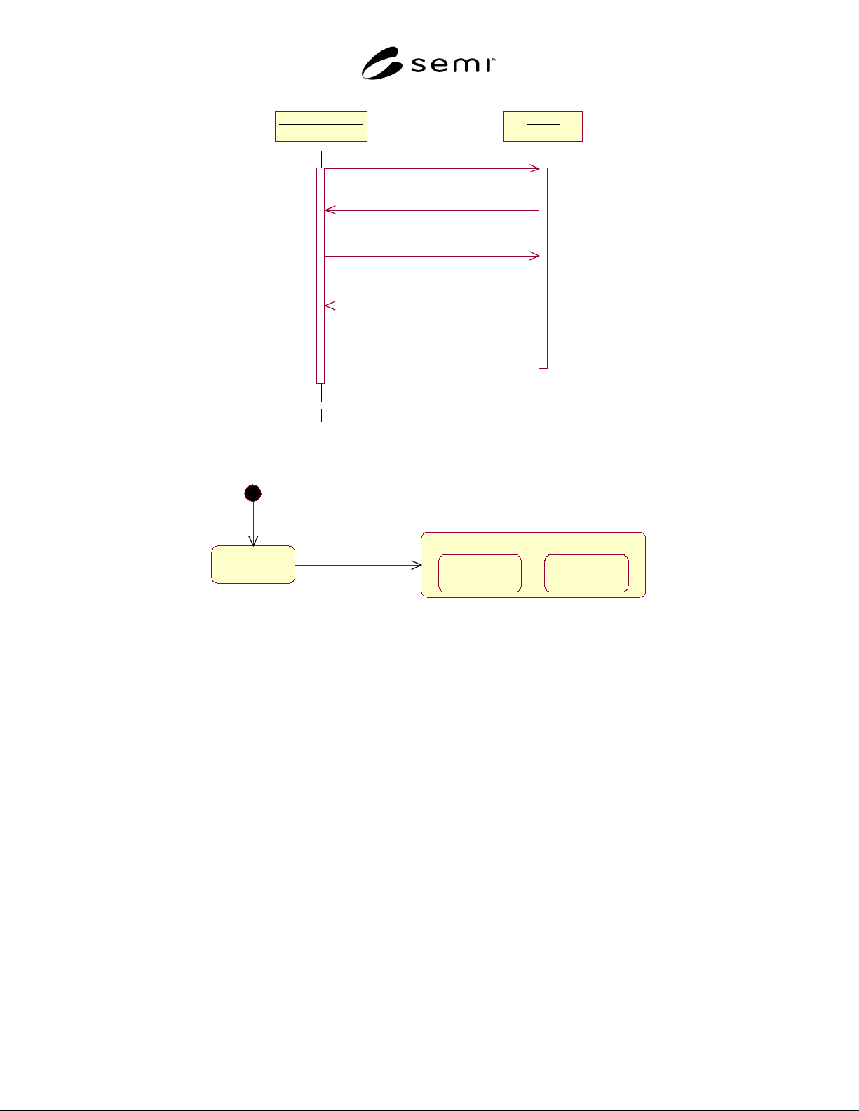
7.4.3.4.1 The Component Interaction Model expresses
framework dynamics by describing the sequence of
collaborations between objects supporting CIM
Framework interfaces. This model is represented using
the UML Sequence Diagram [UML]. The vertical lines
each represent an object that conforms to a role
specified by a CIM Framework interface. This is called
a “lifeline.” The connecting arrows represent messages
that flow between these objects and the data they
convey. Each message must map to a defined operation
on the interface of the message recipient. The example
shown in Figure 24 of a Sequence Diagram models a
portion of the interaction between a bank customer and
an Automated Teller Machine (ATM).
7.4.3.5 State Model
7.4.3.5.1 The State Model shows behavior associated
with CIM Framework interfaces as changes in state that
result from specific events. The required behavior for
an interface is conveyed through UML State Diagrams
[UML] and textual tables that offer supporting details.
Under this notation which is based on Harel Statecharts,
states may be divided into substates, thereby forming a
hierarchy of states. Substates must be one of two types,
termed AND substates (representing concurrency) and
exclusive OR substates (representing a finer breakdown
of a parent state).
7.4.3.5.2 Object State Tables provide supplementary
(to the State Diagram) state information including
descriptive state definitions, state query mechanisms,
the triggers effecting state transition, and the actions
resulting from state transitions.
7.4.3.5.3 Object State Definitions and Query Table
7.4.3.5.3.1 The Object State Definition and Query
Table provide supplementary information to the State
Diagram.
SEMI E81-0600 © 1999, 200037
Bank Customer : B ATM : A
1: requestSession( )
2: requestIdentification( )
3: provideIdentification(idNum ber)
4: verifyIdentification( )
Figure 24
Component Interaction Model Example
State Name
Composite State
State 1 State 2State 1 State 2
s ta t e tr a n si ti on
entry point
Figure 25
State Diagram
7.4.3.5.3.2 Table 1 provides a detailed description of
each object state and identifies the query mechanism for
determining if the object is in that state. Given the
example provided in this section, an entry in the State
Definitions and Query Table would appear as shown.
7.4.3.5.4 Object State Transition Tables
7.4.3.5.4.1 Another supplement to the state model is
the Object State Transition Table (Table 2).
7.4.3.5.4.2 It lists the transition from the state diagram
identified by the starting and ending states, and the
event that causes the transition between these states.
7.4.3.5.4.3 Within the CIM Framework specification,
only those triggers and state changes relevant to
external interfacing are shown to help define how an
external entity (in this case a driver) interoperates with
an object (in this example an automobile).
7.4.3.5.4.4 While this table defines triggers for state
transitions, there is no guarantee that the transition will
take place in response to the trigger. In the above
example, if the car is out of gas the engine will not go
to the running state; if the light is burned out, it will not
transition to the on state; depressing the accelerator
pedal when the auto is in the off state will have no
effect, etc. In the CIM Framework, object state can be
queried to ensure successful transitioning in response to
a triggering message. Events are also used in some
cases to inform the client of a transition or change of
state.