semi合集-English.pdf - 第3908页
SEMI F31-0698 © SEMI 1998 2 chemical until it is transferred to the m anufacturing process. 5.2.6 decont amination — Clean ing u p o f a BCD Syst e m , or any su bsystems th ereof, by introdu cing chemical s ol uti ons i…

SEMI F31-0698 © SEMI 19981
SEMI F31-0698
GUIDE FOR BULK CHEMICAL DISTRIBUTION SYSTEMS
1 Purpose
1.1 This guide defines components of Bulk Chemical
Distribution Systems and sets forth Basic Design
Elements and optional design features common to BCD
Systems.
2 Scope
2.1 This guide applies to BCD Systems used in
semiconductor manufacturing facilities for supplying
liquid chemicals to wafer cleaning and other
manufacturing processes.
3 Limitations
3.1 This guide is not intended to be applicable to every
possible use and type of chemical dispensing system
but only to those systems that originate with sources of
single lots of liquid materials of 55 gallons or more, and
which operate in a way that splits a single liquid stream
into multiple streams. This guide excludes slurry
systems, small liquid chemical dispensing systems,
chemical waste systems, and many other types of
systems that dispense fluids.
3.2 This guide excludes construction protocols for
BCD Systems, such as clean manufacturing practices,
integrity of fabrication, and prequalification of
materials.
3.3 This guide does not intend to cover all the
important safety considerations which relate to Bulk
Chemical Distribution Systems.
3.4 References to “containers” in this document are
not limited to “Bulk Containers” as defined in the Code
of Federal Regulations (CFR) Section 49 or Department
of Transportation (DOT) Regulations.
4 Referenced Documents
NOTE: As listed or revised, all documents cited shall be the
latest publications of adopted standards.
4.1 SEMI Standards
SEMI E49 — Guide for Standard Performance,
Practices, and Sub-Assembly for High Purity Piping
Systems and Final Assembly for Semiconductor
Manufacturing Equipment
SEMI S2 — Environmental, Health, and Safety
Guideline for Semiconductor Manufacturing Equipment
4.2 DOT
1
Department of Transportation
4.3 Federal Regulations
2
49 CFR — Title 49 of the Code of Federal Regulations
5 Terminology
5.1 Acronyms
5.1.1 CDM — Chemical Dispensing Module
5.1.2 CDU — Chemical Dispensing Unit
5.1.3 DIW — Deionized Water
5.1.4 MDU — Modular Dispensing Unit
5.2 Definitions
5.2.1 blending — Combination of two or more
chemicals to create a mixture which contains a desired
ratio of constituents.
5.2.2 chemical dispense system — The module used
for filtering and for dispensing chemical into the
distribution piping network which may be referred to by
a number of manufacturer’s specific designations:
CDM, CDU, and MDU.
5.2.3 chemical reprocessing unit — A subsystem
which purifies or recycles a chemical.
5.2.4 chemical transfer — The technique used to
move chemical between different points in the
distribution system.
5.2.4.1 pressurization — The use of high purity
nitrogen or other appropriate gas to displace liquid
through the distribution system.
5.2.4.2 pumping — A mechanical or pneumatically
operated technique used to create hydraulic force in the
system.
5.2.4.3 hybrid system — A combination of
pressurization and pumping techniques used to transfer
chemical.
5.2.5 day tank — A vessel that stores that amount of
chemical which may be consumed within one or more
days. This holding vessel usually stores prefiltered
1 Department of Transportation, 400 Seventh Street, SW,
Washington, D.C. 20590
2 United States Government Printing Office, Washington, D.C. 20402

SEMI F31-0698 © SEMI 1998 2
chemical until it is transferred to the manufacturing
process.
5.2.6 decontamination — Cleaning up of a BCD
System, or any subsystems thereof, by introducing
chemical solutions into the piping systems. This
procedure occurs during qualification and prior to
commissioning the system.
5.2.7 dilution — Combination of a concentrated
chemical and DIW to create a lower concentration of
the aqueous chemical.
5.2.8 on-site gas-to-chemical generation — The
contacting of a liquid and gas phase to create a stable
liquid solution. The chemical is generated on-site in a
form suitable for distribution through a dispense
system.
5.2.9 pickling — Conditioning of the system by filling
it with the actual chemical or another chemical for
which the system is designed. This chemical will stay in
the system for a specified period of time. The purpose
of this conditioning is to leach out impurities prior to
actually using any chemical in the manufacturing
process.
5.2.10 polishing — The process of flowing chemical
through a filter one or more times to reduce the
particulate levels of the chemical.
5.2.11 primary containment — Tubing, piping, or
components whose wetted surface is directly in contact
with the chemical. These components are generally
made from fluoropolymer materials such as
Perfluoroalkoxy (PFA).
5.2.12 secondary containment — Tubing or piping
which contains the primary piping or tubing. The
purpose of this configuration is to control leaks and to
protect against spills. Secondary containment of solvent
systems generally uses stainless steel material, and acid
or base systems generally use Schedule 40
Polyvinylchloride (PVC) material boxes such as VMB.
This may also be used as secondary containment.
5.2.13 stabilized filtration — A design feature that
provides for the continuous flow of chemical through
filters to minimize shocking and pulsating of the filters.
5.2.14 surge suppression — Use of a device or in-line
chamber that minimizes flow pulsations caused by a
pump. This may also be referred to as pulsation
dampener.
5.2.15 valve manifold box (VMB) — A chemical-
resistant enclosure which houses manual and/or
pnuematically actuated valves, tees, and fittings.
5.2.16 vessel — A vessel fabricated from or
containing an inner lining of chemically inert and
resistant materials which is specifically designed to
maintain the purity level of the chemical for a long
period of time. All containers are fabricated from or at
least contain an inner lining of chemically inert and
resistant materials and are specifically designed to
maintain the purity level of the chemical for long
periods of time. The larger containers are generally
designed in conformance to Department of
Transportation Regulations (DOT) and may be
transported by ground. These containers have fittings
which are compatible to this purpose so that they may
be hooked up to the BCD Systems directly. Such
containers include:
5.2.16.1 drum — A container for storing chemicals,
generally with a cylindrical shape and not more than 55
gallons or 200 liters in size.
5.2.16.2 tote — A container for storing chemicals,
generally 110, 220, or 330 gallons in size and requiring
an outer shell to provide structural support to the vessel.
5.2.16.3 ISO container — A container for storing
chemicals, usually large in size, able to be transported
directly, and designed in compliance with criteria from
the International Standards Organization.
5.2.17 wetted surface — Any surface which comes
into contact with the chemical.
6 General Requirements
6.1 Materials — Components of the BCD Systems
must be appropriate to the application and conform to
electrical, mechanical, and chemical requirements as
defined by the physical installation environment, local
and national code interpretations, process requirements,
and delivery specifications.
6.2 System Installation — The Bulk Chemical
Distribution System is installed according to a protocol
which ensures mechanical integrity, leakproof
operation, and minimal contamination to any liquids
being distributed throughout the system.
6.2.1 System Installation procedures include a
rinsedown protocol which may include any of the
following: (1) a flushing procedure with DIW; (2) a
sanitization step using hydrogen peroxide; (3) a drying
step using nitrogen gas; and (4) a “pickling” process
using the actual chemical, or a less concentrated form
of the chemical. For solvent systems, the rinse-down
chemicals introduced are generally the same as the
solvent that is designated to be used in the system,
whereas for acid systems, the rinse down solutions may
include DIW, ozonated water, or a dilute form of
hydrogen peroxide.
6.2.2 The protocol for System Installation and start-up
follows a predefined sequence of events which
SEMI F31-0698 © SEMI 19983
incorporates all of the physical activities and testing
parameters and establishes check points for approvals at
each stage.
6.3 Acceptance Tests — Acceptance tests are
conducted on each subsystem or system produced. They
are the basis for acceptance or rejection by the
purchaser.
6.3.1 Acceptance testing may include performance
demonstrations, demonstration of reliability criteria,
and achievement of purity standards. Safety
considerations are addressed elsewhere.
6.4 Qualification Testing — Qualification testing is
performed on the liquid chemicals being transported
through each chemical piping subsystem.
6.4.1 Qualification testing may include tests for trace
metals, anions, particles, and total organic carbon.
Assay analysis is recommended for blending or dilution
operations.
6.5 Chemical Specifications — Particulate BCD
Systems are specified as to the level of impurities at the
point of use as compared to the quality of the incoming
chemical. Impurities in the chemical are generally
specified in terms of particles per ml; metallic
impurities are specified for each element and for total
adders; and organic impurities are specified for total
added.
7 Basic Design Elements
7.1 General — Each Bulk Chemical Distribution
System contains certain basic components and a variety
of design options to meet particular customer and
facility needs. A simple example system is shown in
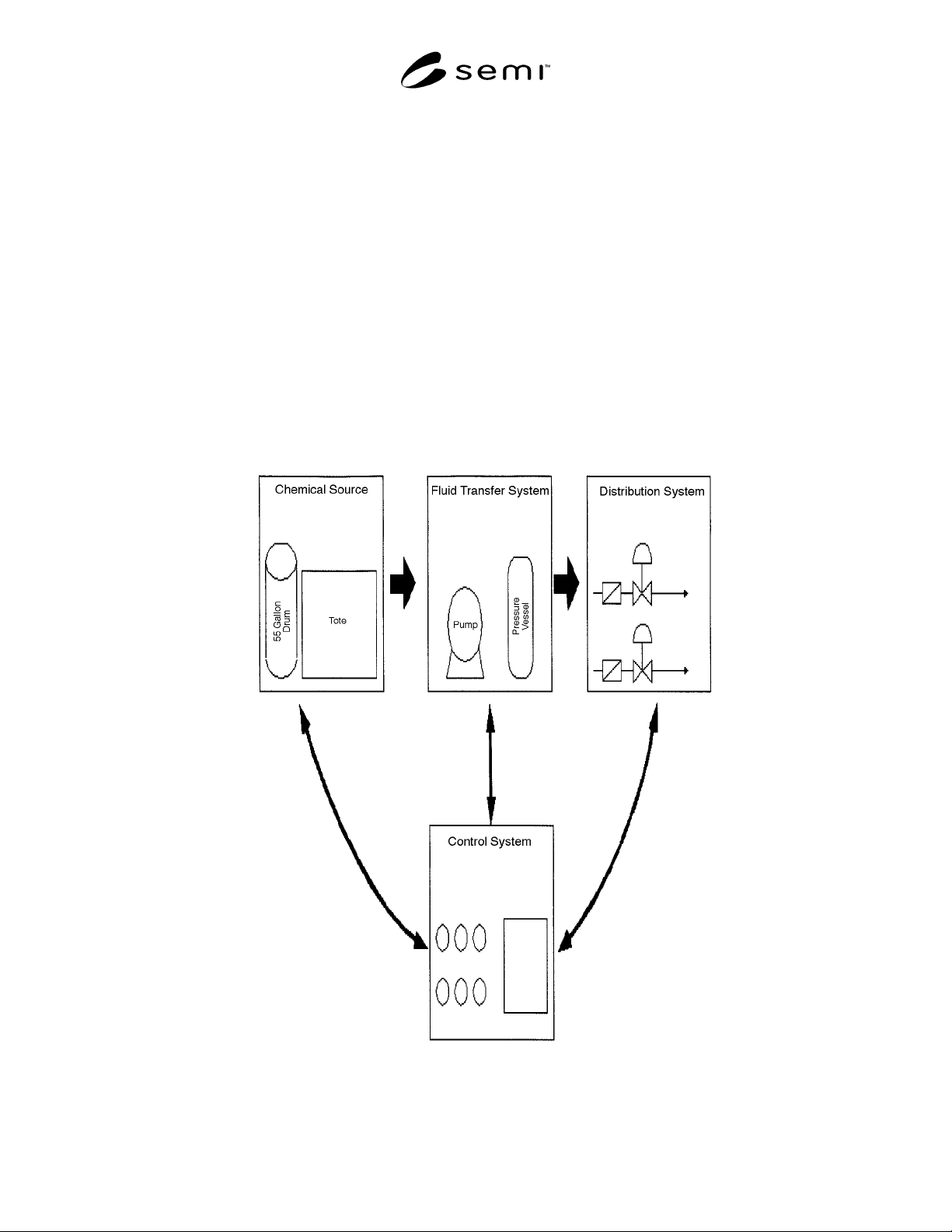
Figure 1.
Figure 1
Schematic of Basic Bulk Chemical Distribution System