semi合集-English.pdf - 第525页
SEMI E76-0299 SEMI 1998, 1999 5 should be consistent with those d efined in the Facilities Interface Specification and s hould n ot deviate from equipm ent to equipm ent of a s p ecific m odel and revisi on. EPOC…

SEMI E76-0299
SEMI 1998, 1999
4
Table 2. EPOC Consistency Recommendations
Equipment Delivered Compared to EPOC Locations EPOC Types EPOC Sizes
Supplier-provided Facilities Interface
Specification
Should match Should match Should match
Similar Equipment (Same Model and Revision)
for Same Process Application
Should match Should match Should match
Similar Equipment (Same Model and Revision)
for Different Process Application
Should match for same
utilities.
Could match unique
utilities to unique
locations within the
appropriate EPOC
group.
Should match Could match, technical
reasons should exist
for differences.
Similar Equipment (Different Model) for Same
Application
Could match Could match Could Match
6 EPOC Recommendations
6.1 Equipment Point of Connection Locations
6.1.1 Table 1, EPOC Location Recommendations
identifies the locations for the specified facility utility
services. The locations noted apply to all equipment
types, as listed in the document scope, and all
equipment configurations including but not limited to
boxed equipment, linked equipment, and cluster
equipment.
6.1.2 Bottom Location Plane: Facility services are
typically provided from the subfab below the waffle
slab. The bottom location of EPOC’s allows for straight
up routing of supply lines, thus reducing equipment
footprint and easing facilitation. The locations of
EPOC’s need to be readily accessible to facilitate hook-
up to the UPOC (i.e., accessible from the back or sides).
(See Table 1.)
6.1.3 Back Location Plane: If the bottom location
plane option is not utilized for hookup, EPOC’s should
be on back plane of equipment just above the raised
floor. (See Table 1.)
6.2 Equipment Point of Connection Groups
6.2.1 Equipment points of connection should be
grouped together by service type to ensure ease of
hookup and qualification of the equipment. The
following groups should be considered during the
configuration of the equipment.
a) Electrical Power Connections Includes but
is not limited to connections for main electrical
utility power supply.
b) Data Communications Connections
Includes but is not limited to factory systems,
automated material handling system, and
support equipment communication cables and
interface connectors.
c) Gas Delivery System Connections Includes
but is not limited to fittings for bulk and
specialty gas lines.
d) Liquid Delivery System Connections
Includes but is not limited to fittings for liquid
chemical, slurry, ultra pure water, process
cooling water, temperature control unit fluids,
and industrial water lines.
e) Equipment Effluent Connections Includes
but is not limited to fittings for exhaust, drain,
and vacuum lines.
f) Life and Safety System Connections
Includes but is not limited to fire protection,
leak detection, emergency machine off (EMO),
and hazard warning systems.
6.2.2 A hierarchy should be adhered to when locating
these groups of connections on equipment. Data
communication wiring should be routed separately from
power wiring and connections. Radio frequency (RF)
interconnects should be routed and grouped separately.
All electrical and electronic wiring should be away from
and above water and drain lines.
6.3 Equipment Point of Connection Consistency
6.3.1 This section provides key elements to ensure the
required consistency of the equipment points of
connection. Connection locations on the equipment

SEMI E76-0299
SEMI 1998, 1999
5
should be consistent with those defined in the Facilities
Interface Specification and should not deviate from
equipment to equipment of a specific model and
revision. EPOC tolerances need to be +/- 6.35 mm (+/-
1/4 inch) in all directions as measured from the supplier
defined equipment datum point. Tighter tolerances
should be considered for inflexible or difficult to move
hookups such as large diameter (over 2 inch) exhaust or
water lines. Connector sizes and types should match
exactly.
6.3.2 Table 2 - EPOC Consistency Recommendations
identify equipment variations and levels of consistency
required for equipment points of connection location,
connector type and size.
6.3.3 In Table 2, the term “Should Match” identifies
areas that have traditionally been the most costly and
where significant gains can be made in achieving
installation efficiency . The term “Could Match”
identifies areas where modest gains can be made in
installation efficiency .
6.4 Equipment Point of Connection Reduction
6.4.1 The number of connection points to the
equipment should be kept to a minimum. The EPOC’s
located on wafer processing equipment should follow a
strategy commonly referred to as single line drops,
where there is only one point of connection per service
per piece of equipment. Where feasible, distribution of
a particular facility (e.g., chilled water, waste drains for
the same type of chemicals) should be distributed
through internal manifolding. Internal equipment
manifolding should be configured to allow for
configurable equipment sub-systems like process
chambers and gas panels. In addition to manifolding, all
other interface box functions should be configured on-
board the equipment this includes any required shut-off
valves, regulators, filters, QC sample valves and
pressure indicators.
6.5 Equipment Point of Connection Interface Panel
6.5.1 Once EPOC locations and groupings have been
defined and standardized for purposes of consistency,
the supplier could utilize an interface panel concept for
simplifying equipment hook-up. The interface panel
should consist of a physical panel that becomes part of
the permanent equipment installation. All EPOC’s
should be comprehended in the layout of the interface
panel using the recommendations for location,
grouping, and consistency as discussed in Sections 6.1,
6.2, and 6.3. The supplier should design a standard
interface panel layout that supports a given equipment
type and all associated revisions.
6.5.2 Common connector technologies, types, and
sizes should be utilized along with provisions for
containment of hazardous materials. Typically,
hazardous production material connections are
contained within the equipment
6.5.3 Spacing of multiple gas and liquid connections
on the interface panel should provide sufficient access
and spacing for installation and maintenance for
multiple lines (i.e., orbital weld head, wrench, and test
fittings).
7 Pre-facilitation Recommendations
7.1 The pre-facilitation strategy should provide the
device manufacturer with the ability to efficiently and
accurately install UPOC’s prior to equipment delivery,
allowing immediate hook-up of the equipment upon
arrival to the fab. The equipment supplier should
provide a template and/or jig, as well as a EPOC
interface panel (if applicable) or pre-facilitation
pedestal prior to the equipment delivery as part of a
strategy to support accurate pre-facilitation of utility
points of connection. In situations where a pedestal is
being utilized (see Section 7.4), the pedestal can serve
as an aide to pre-facilitation. The supplier and device
manufacturer should discuss and agree on the chosen
strategy.
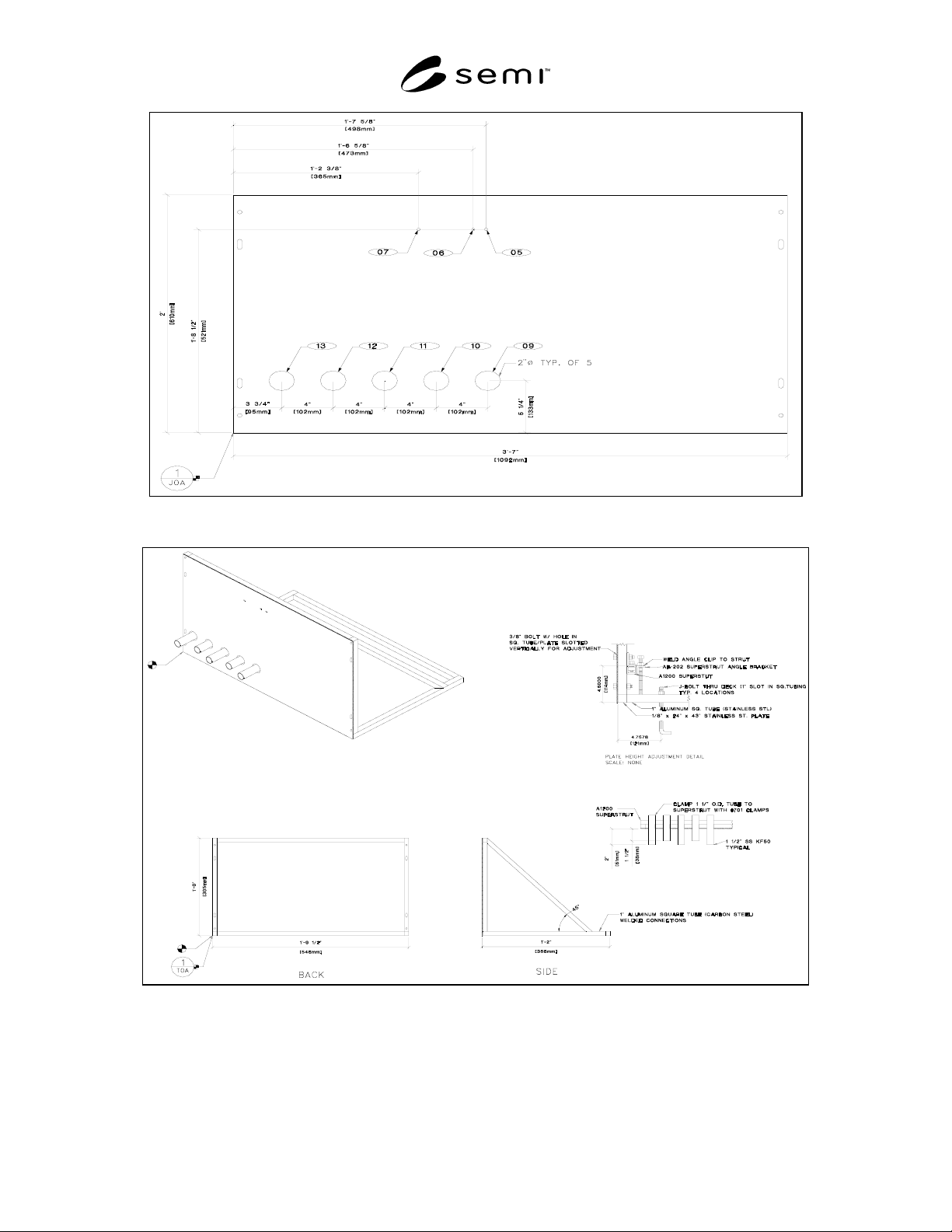
7.2 Templates: The template provides a two-
dimensional guide that projects EPOC locations to a
two-dimensional surface, typically the floor. This would
allow the device manufacturer to open popouts, core
holes, etc., and pre-facilitate to a point close to, but not
necessarily including, the UPOC. See Figure 1 for a
representative example of a Template.
7.3 Jigs: The jig provides a guide that locates the -
EPOC’s in three-dimensional space. This would allow
the device manufacturer to pre-facilitate to the UPOC’s
or at least prefabricate the facility lines and UPOC’s
such that final hookup could be accomplished
immediately after setting the equipment. See Figure 2
for a representative example of a Jig.
7.4 Pre-facilitation Pedestal: Application notes and
three representative examples of using pedestals to
support pre-facilitation are included in the related
information section at the end of this document.
SEMI E76-0299
SEMI 1998, 1999
6
Figure 1
Template Example
Figure 2
Jig Example