semi合集-English.pdf - 第3994页
SEMI F45-0699 © SEMI 1999 2 Figure 3B Dimensions of Reducing Elbow Weld Fittings Figure 4A Dimensions of Reduci ng Tee Weld Fittings NOT E 1: Mach ined tube w eld e nds sha ll be s quare t olerance ± 0.5° . NOT E 2: I nt…
SEMI F45-0699 © SEMI 19991
SEMI F45-0699
GUIDELINE FOR STANDARDIZATION OF MACHINED STAINLESS
STEEL REDUCING WELD FITTINGS
This guideline was technically approved by the Global Facilities Committee and is the direct responsibility of
the Japanese Facilities Committee. Current edition approved by the Japanese Regional Standards Committee
on March 17, 1999. Initially available on www.semi.org May 1999; to be published June 1999.
1 Purpose
1.1 The purpose of this guideline is to prevent
confusion among the manufacturers of stainless steel
reducing weld fittings, piping fabricators and end users
and to standardize the dimensions of weld fittings.
2 Scope
2.1 This guideline applies to 6.35 mm (1/4 in.), 9.53
mm (3/8 in.) and 12.7 mm (1/2 in.); the machined
stainless steel reducing weld fittings elbows and tees
made for use in the semiconductor industry.
3 Referenced Documents
3.1 None.
4 Terminology
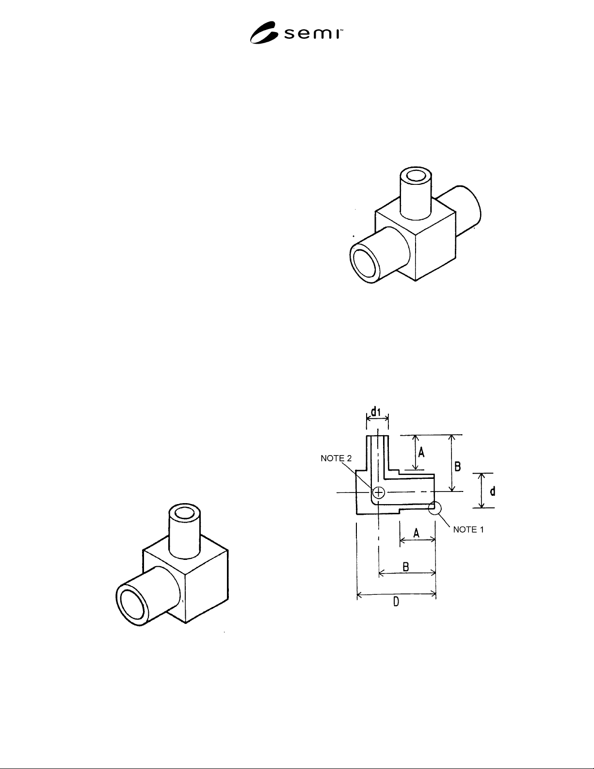
4.1 reducing elbow weld fittings machined fittings
shaped like the letter "L", for welding tubes in a right
angle. (see Figure 1)
4.2 reducing tee weld fittings machined fittings
shaped like the letter "T", for welding tubes in a T-
shape. (see Figure 2)
4.3 reducing weld fittings machined fittings to be
welded or welded fittings.
Figure 1
Reducing Elbow Weld Fittings
Figure 2
Reducing Tee Weld Fittings
5 Dimensions of Reducing Weld Fittings
5.1 Reducing Elbow Weld Fittings (see Figures 3A and
3B)
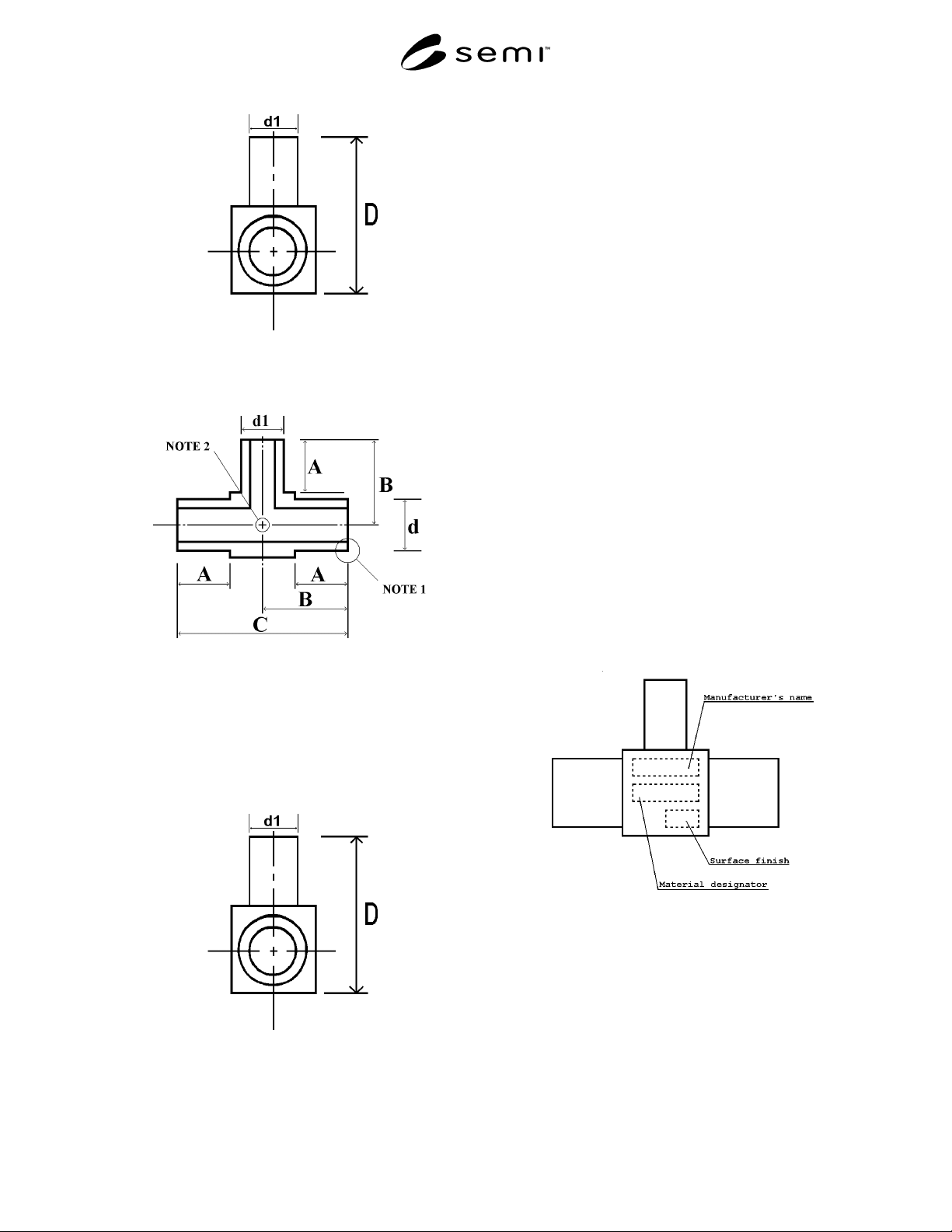
5.2 Reducing Tee Weld Fittings (see Figures 4A and
4B)
Figure 3A
Dimensions of Reducing Elbow Weld Fittings
NOTE 1: Machined tube weld ends shall be square tolerance ±
0.5°.
NOTE 2: Intersection shall be square tolerance ± 0.5°.
SEMI F45-0699 © SEMI 1999 2
Figure 3B
Dimensions of Reducing Elbow Weld Fittings
Figure 4A
Dimensions of Reducing Tee Weld Fittings
NOTE 1: Machined tube weld ends shall be square tolerance ±
0.5°.
NOTE 2: Intersection shall be square tolerance ± 0.5°.
Figure 4B
Dimensions of Reducing Tee Weld Fittings
6 Marking the Reducing Weld Fittings
6.1 Marks include 1), 2), 3), 4), 5), 6) and 7). Marks
1) through 4) shall be made on the reducing weld
fittings body. Marks 5) - 7) shall be made on the
reducing weld fittings body or its package (both
individual bagging and box).
1) Manufacturer's name
2) Material designator
3) Surface finish designator
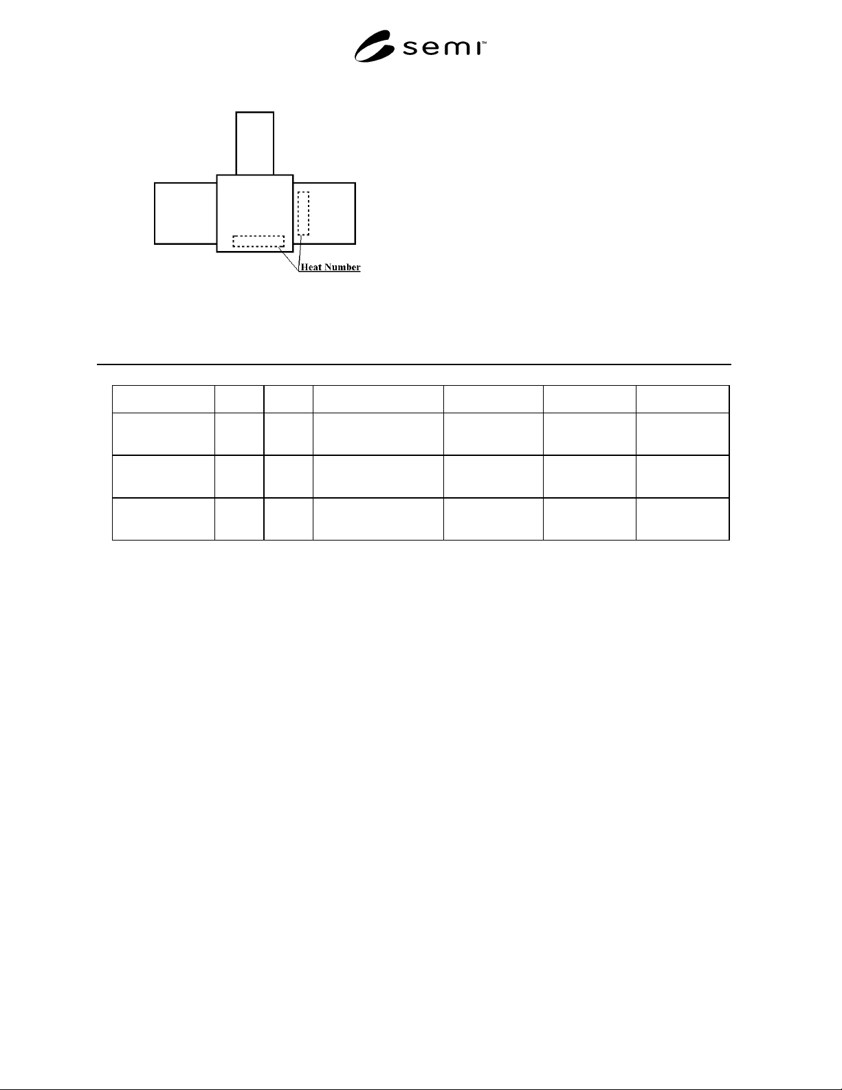
4) Heat Number
5) Lot Number (optional)
6) Model (Part Number)
7) Wall thickness of tube end
6.2 To be agreed upon between supplier and user for
marking items and marking locations. The example
below explains marking applications. (see Figures 5A
and 5B)
6.3 Manufacturer's name, Material designator, Surface
finish designator and Heat Number should be marked
on the body. The Heat Number shall be marked either
on the body of the cube along with the other
information, but if space is limited, then the Heat
Number marked on the tube Outside Diameter close to
the body is permissible.
Figure 5A
Marking Application Example
SEMI F45-0699 © SEMI 19993
Figure 5B
Marking Application Example
7 Outside Diameter Toleran ce
7.1 The Outside Diameter tolerance of 6.35 mm (1/4
in.), 9.53 mm (3/8 in.) and 12.7 mm (1/2 in.) is + 0.1
mm, - 0.0 mm (+ 0.004 in., - 0.000 in.).
8 Wall Thickness of Tube E nd
8.1 Wall thickness of tube end should be either 1 mm
(0.039 inch) or 0.89 mm (0.035 inch), 1.24 mm (0.049
inch) and the thickness should be marked on the
reducing weld fitting body or its package. Wall
thickness tolerance is ± 8%.
Table 1 Dimensions and Tolerance
Nominal Diameter d d1 A B C D
9.53 × 6.35
(3/8 × 1/4)
9.53
(0.375)
6.35
(0.25)
6.35 + 0.1/ - 0.05
(0.25 + 0.004/ - 0.002)
11.9 ± 0.1
(0.4685 ± 0.004)
23.8 ± 0.1
(0.937 ± 0.004)
17.45 ± 0.1
(0.687 ± 0.004)
12.7 × 6.35
(1/2 × 1/4)
12.7
(0.5)
6.35
(0.25)
6.35 + 0.1/ - 0.05
(0.25 + 0.004/ - 0.002)
13.5 ± 0.1
(0.5315 ± 0.004)
27.0 ± 0.1
(1.063 ± 0.004)
20.65 ± 0.1
(0.813 ± 0.004)
12.7 × 9.53
(1/2 × 3/8)
12.7
(0.5)
9.53
(0.375)
6.35 + 0.1/ - 0.05
(0.25 + 0.004/ - 0.002)
13.5 ± 0.1
(0.5315 ± 0.004)
27.0 ± 0.1
(1.063 ± 0.004)
20.65 ± 0.1
(0.813 ± 0.004)
Dimensions: mm (in.)
NOTICE: These standards do not purport to address
safety issues, if any, associated with their use. It is the
responsibility of the user of these standards to establish
appropriate safety and health practices and determine
the applicability of regulatory limitations prior to use.
SEMI makes no warranties or representations as to the
suitability of the standards set forth herein for any
particular application. The determination of the
suitability of the standard is solely the responsibility of
the user. Users are cautioned to refer to manufacturer's
instructions, product labels, product data sheets, and
other relevant literature respecting any materials
mentioned herein. These standards are subject to
change without notice.
The user's attention is called to the possibility that com-
pliance with this standard may require use of copy-
righted material or of an invention covered by patent
rights. By publication of this standard, SEMI takes no
position respecting the validity of any patent rights or
copyrights asserted in connection with any item men-
tioned in this standard. Users of this standard are ex-
pressly advised that determination of any such patent
rights or copyrights, and the risk of infringement of
such rights are entirely their own responsibility.
Copyright by SEMI® (Semiconductor Equipment and Materials
International), 3081 Zanker Road, San Jose, CA 95134. Reproduction o
f
the contents in whole or in part is forbidden without express written
consent of SEMI.