semi合集-English.pdf - 第4017页
SEMI F49-0200 © SEMI 2000 3 Utility Supplied Power Facilities Electric al Distribution Sy ste m Infrastruct ure Equipme nt Process Equipme nt Support Equipme nt Utilit y Services Facilities Sy stems Wafe r Processing Sy …

SEMI F49-0200 © SEMI 2000 2
SEMI E51 — Guide for Typical Facilities Services and
Termination Matrix
4.2 IEEE Standards
1
IEEE 1100 — IEEE Recommended Practice for
Powering and Grounding Sensitive Electronic
Equipment
IEEE 1159 — IEEE Recommended Practice on
Monitoring Electrical Power Quality
IEEE 1346 — IEEE Recommended Practice for
Evaluating Electric Power System Compatibility with
Electronic Process Equipment
NOTE 1: As listed or revised, all documents cited shall be the
latest publications of adopted standards.
5 Terminology
5.1 facilities infrastructure equipment — component,
modules, and systems used to transport materials like
chemicals, power, water, effluent, and exhaust in
semiconductor factories.
5.2 process equipment — fabrication equipment,
inspection equipment, and cassette stage equipment
used in semiconductor manufacturing.
5.3 support equipment — ancillary equipment not part
of the process equipment main chassis.
5.4 voltage sag — an rms reduction in the ac voltage,
at power frequency, for durations from half-cycle to a
few seconds.
6 Impact
6.1 The primary goal of this guide is mitigation of the
effects of utility voltage sags on semiconductor
processing equipment, support equipment, and facilities
infrastructure equipment. A voltage sag event
adversely affecting only one of these pieces of
equipment can cause processing equipment to
malfunction. Both the direct and indirect effect of
voltage sags on process equipment should be managed.
Voltage sags can effect process equipment directly
through the electrical power points of connection.
Voltage sags can also indirectly effect process
equipment through fluctuations in air, gas, liquid, and
other utility streams caused when voltage sags effect
support equipment and facility infrastructure
equipment.
6.2 Examples of processing equipment, support
equipment, and facilities infrastructure equipment are
1 The Institute of Electrical and Electronic Engineers, Inc. (IEEE),
345 East 47th Street, New York, NY 10017-2394, USA
listed below. The interaction of these three types of
equipment is shown in Figure 1.
6.2.1 Process Equipment
• Etch (dry & wet)
• Film deposition (CVD & PVD)
• Thermal
• Surface prep and clean
• Photolithography (exposure & coater/developer)
• Chemical Mechanical Polishing
• Ion Implant
• Metrology
• Automated test
6.2.2 Support Equipment
• Vacuum system (roughing, turbo, and cryogenic
pumps)
• RF generator
• Residual gas analyzer (RGA)
• Water heater
• Chiller
• Photolithography stepper laser light source power
supplies
• Photolithography coat/developer temperature/
humidity controllers
• Emission control (burn boxes)
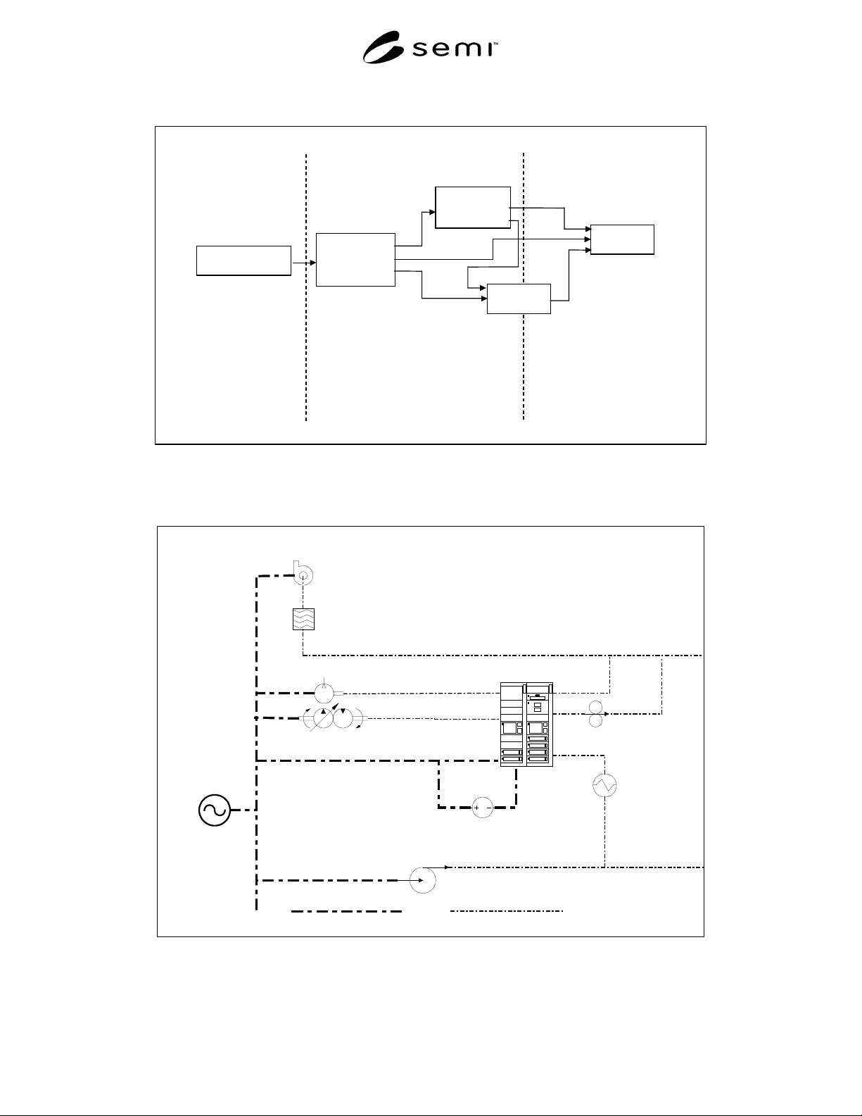
SEMI F49-0200 © SEMI 20003
Utility Supplied
Power
Facilities
Electrical
Distribution
System
Infrastructure
Equipment
Process
Equipment
Support
Equipment
Utilit
y
Services
Facilities
Systems
Wafe
r
Processing
Systems
Power Monitoring
and Conditioning
Power Monitoring
and Conditioning
Ride-Through
Techniques
See industry guide for
electric utility voltage
sag performance.
Covered in this guide for
semiconductor factory systems
voltage sag immunity
See industry specification and
test method for semiconductor
processing equipment voltage
sag immunity.
Ride-Through
Techniques
Figure 1
Power Quality Interfaces
(See Related Documents section.)
Scrubber Exhaust Distribution
Fume Scrubber
Scrubber Fan
Process Cooling Water
Distribution
PCW Pump
Process Vacuum
Pump & Motor
Process Vacuum
Distribution
Clean Dry Air Distribution
CDA Motor &
Compressor
Power Source
Wafer Processing
Tool
Power
Process Mechanical
Fab Power
Distribution
Tool High
Vacuum Pump
Tool Closed
Loop Chiller
DC
Tool RF
Generator
Figure 2
Typical Interconnection of Facility Infrastructure Equipment with Process and Support Equipment

SEMI F49-0200 © SEMI 2000 4
6.2.3 Facilities Infrastructure Equipment
• Exhaust systems (scrubbers and VOC exhaust fans
and controls)
• Process cooling water system (pumps and controls)
• Air compressors (and controls)
• Vacuum system (pumps and controls)
• Bulk and specialty gas distribution systems (pumps
and controls)
• Liquid chemical distribution systems (pumps and
controls)
• Power distribution systems
7 Power Monitoring and Co nditioning
Recommendations
7.1 Reasons for Monitoring and Conditioning
7.1.1 Semiconductor manufacturing facility electrical
distribution systems should be designed to transport
power to process equipment, support equipment, and
other facilities infrastructure equipment without
degradation to the electrical power quality. The system
should recognize electrical power that does not meet
specification and provide proper power conditioning so
as not to impact wafer processing.
7.1.2 Power monitoring is used to measure electrical
system power quality performance for the following
reasons.
a) Monitoring data can be compared to
equipment voltage sag specifications to
identify problems.
b) Selection and control of power conditioning
devices are dependent upon monitoring
measurements.
7.1.3 Power conditioning is implemented to correct for
gaps in equipment voltage sag susceptibility and point
of connection electrical power performance. Power
conditioning is occasionally implemented where the
risk of unacceptable equipment performance is high,
where equipment performance tolerance is outside
specifications, and where equipment interruption is
costly.
7.2 Monitoring and Conditioning Program
7.2.1 Quantify the process equipment, support
equipment, and facilities infrastructure equipment
voltage sag susceptibility using industry standard
specifications and test methods. (See Sections 7.3 and
7.4.)
7.2.2 Set-up monitors for utility power quality (see
Section 7.5).
7.2.3 Measure and/or model the impact of the facility
electrical distribution system on the utility power
delivered to the process equipment (see Section 7.6).
7.2.4 Model and evaluate cost/benefit of power
conditioning solutions where there are gaps or high
risks. Select and implement identified power
conditioning solutions into the facilities electrical
distribution system. (See Section 7.7.)
7.2.5 Maintain the installed power conditioning
equipment and monitor the power either continuously
or periodically to assure performance and evaluate
results.
7.3 Process Equipment Performance
7.3.1 Facility design specifications should include
requirements for processing equipment voltage sag
immunity (see industry specification for semiconductor
processing equipment voltage sag immunity). (See
Related Documents section.)
7.3.2 Variability in process equipment manufacturing
and supplied utility power quality preclude interruption
free manufacturing. This variation comes from
multiple sources:
a) Verification of representative samples of
equipment does not guarantee 100% of the
equipment will meet the same requirements.
b) Factors such as location, load changes,
capacity, weather, and transmission/
distribution equipment, limit how well utility
power quality can be controlled.
c) The tests, themselves, are not variation free;
the test equipment, calibration processes, and
the test personnel can introduce further
variability.
7.3.3 The risk of manufacturing interruptions can be
considerably reduced through two approaches.
a) Create a margin between allowable voltage sag
for the supplied utility power and process
equipment voltage sag immunity.
b) Provide added protection from interruptions
due to voltage sag events by enhancing the
power quality in the facilities distribution
system. (This approach is covered in this
document, see Scope and the middle segment
of Figure 1.)