semi合集-English.pdf - 第4125页
SEMI F62-0701 © SEMI 2001 5 Figure 1b Gas Temperature Effect T est Ap paratus NOT E 5: Flow Sta ndard may be located upstr eam or down stre am. Step m T em 1. T min 2. T min + 1/4 (T max - T min ) 3. T min + 1/2 (T max -…
SEMI F62-0701 © SEMI 2001 4
15.1.3 The gas temperature coefficient of flow is to be
calculated as follows:
100 x
)1
T
- 2
T
( x
Q
1
Q
- 2
Q
= C)(%/
TC
gg
sp
aa
g
°
where Q
a1
and Q
a2
are the actual flow rates measured at
gas temperatures T
g1
and T
g2
respectively. For zero
setpoint use the following.
100 x
)1
T
- 2
T
( x
Q
1
Q
- 2
Q
=
TC
gg
fullscale
aa
zero
This yields a result expressed as a percent of reading
per °C. Refer to Table 5 for an example of data
collection and analysis. Final TCg is to be presented in
Table 1 format.
16 Reporting Results
NOTE 4: All special features (remote electronics, auto zero,
etc.) should be noted on the testing results for comparative
analysis.
16.1 The gas temperature coefficient at each flow rate
is to be displayed as shown in Table 1.
16.2 The gas temperature coefficient data from Table
1 is to be displayed as shown in Figure 5. The gas
temperature, actual flow, and indicated flow are to be
displayed versus time as shown in Figure 6.
16.3 The ambient temperature coefficient is to be
presented in tabular form as shown in Table 2.
16.4 The data for the steady-state effect from Table 2
should be presented as shown in Figure 7. The data for
the transient effect from Table 4 should be presented as
shown in Figure 8.
17 Illustrations
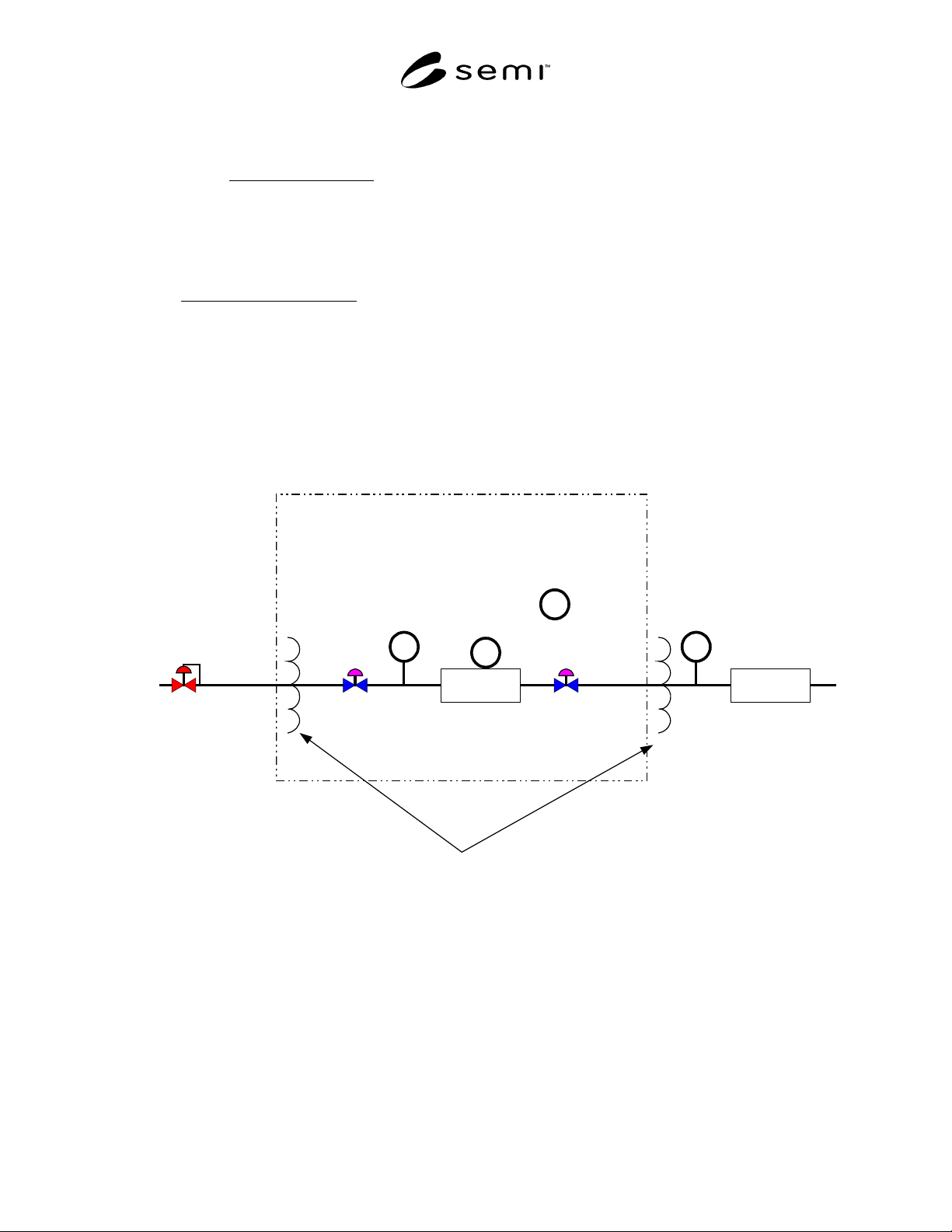
Figure 1a
Ambient Temperature Effect Test Apparatus
DUT
Flow
Standard
Temperature Controlled
Environment
Tg
TE
Ts
N2 in
Heat Exchangers
Vii Vio
TA
SEMI F62-0701 © SEMI 20015
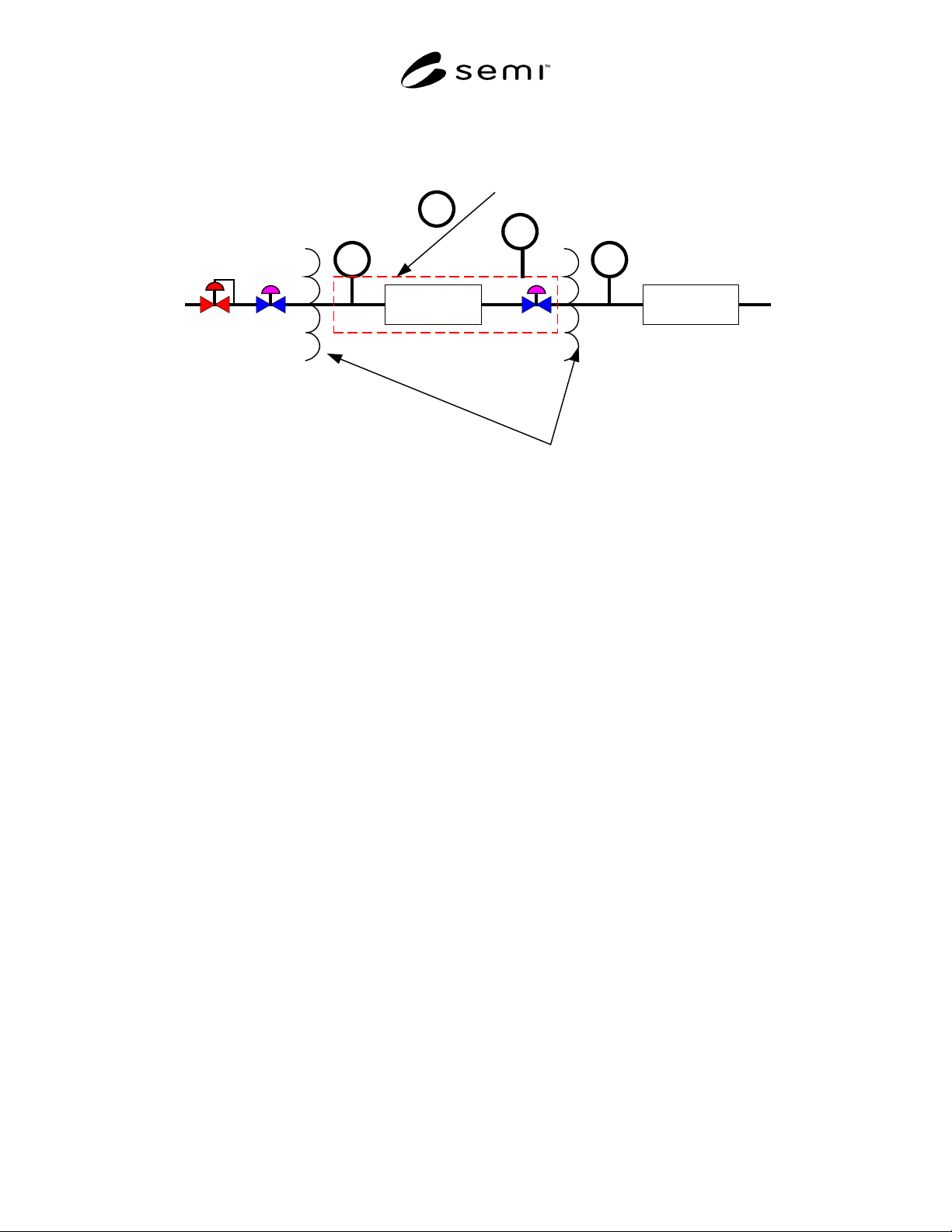
Figure 1b
Gas Temperature Effect Test Apparatus
NOTE 5: Flow Standard may be located upstream or down stream.
Step m T
em
1. T
min
2. T
min
+ 1/4 (T
max
- T
min
)
3. T
min
+ 1/2 (T
max
- T
min
)
4. T
min
+ 3/4 (T
max
- T
min
)
5. T
max
6. T
min
+ 3/4 (T
max
- T
min
)
7. T
min
+ 1/2 (T
max
- T
min
)
8. T
min
+ 1/4 (T
max
- T
min
)
9. T
min
Figure 2
Ambient Temperature Setpoint (T
em
)
DUT
Tg
Flow
Standard
Ts
Hot Plate or Heater Tape
Surrounding MFC Base
not MFC electronics
N2
Heat Exchangers
TB
TE
Vii Vio
SEMI F62-0701 © SEMI 2001 6
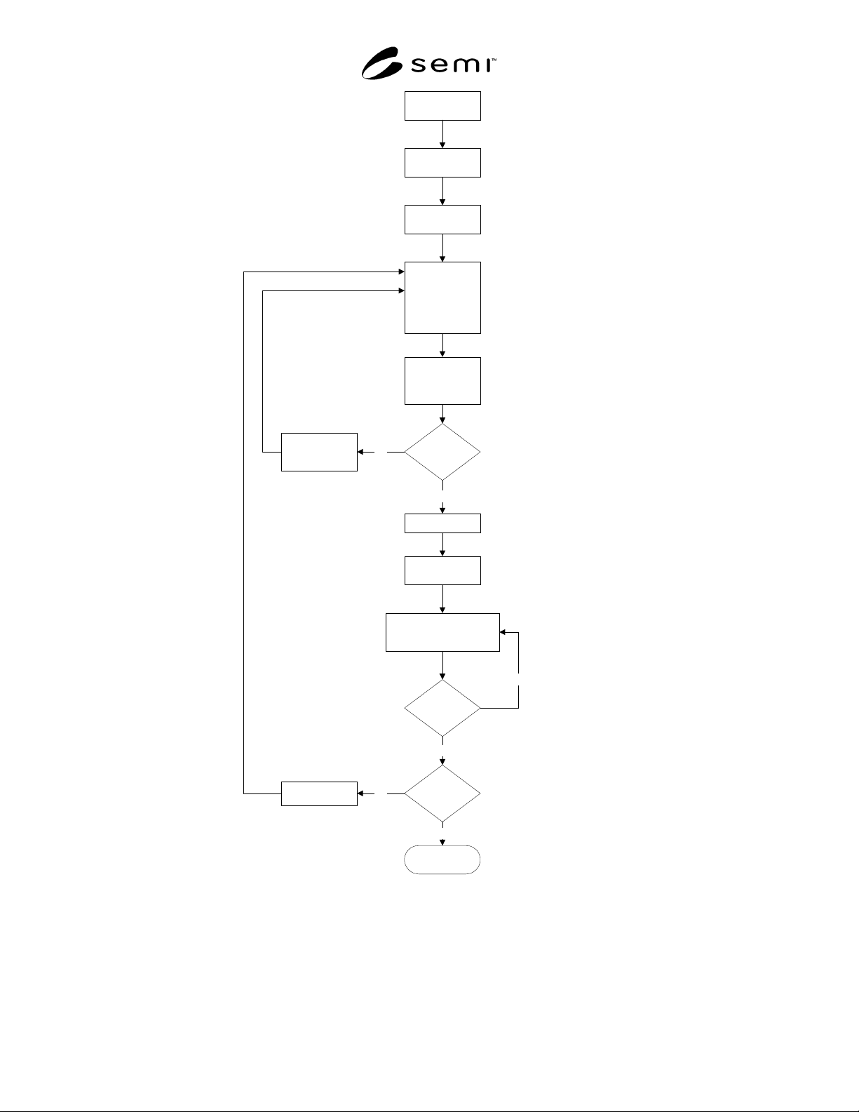
Figure 3
Ambient Temperature Test Procedure Flow Chart
Install DUT
M=1
Tem=Tmin
MFC Setpoint
N=1 0%
N=2 25%
N=3 50%
N=4 75%
N=5 100%
Record Tem &
Qam @ time
intervals 10 Times
N=5
Setpoint=0
N=N+1
Set
Te=Te(M+1)
Record Te and Qind for zero
setpoint @ time intervals
Te Stable?
M=8 ?
END
M=M+1
No
Yes
No
Yes
Yes
No