semi合集-English.pdf - 第1896页
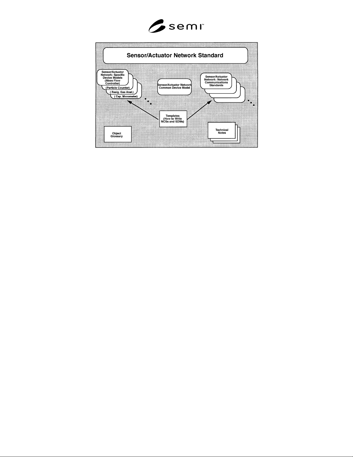
SEMI E54.1-1000 © SEMI 1996, 2000 2 Figure 1 Sensor/Actuato r Network-Related Do cuments 5 Terminology Termin ology may be reproduced h ere which is defined in oth er SEMI documents. 5.1 Device C omponent Ter minolo g y …

SEMI E54.1-1000 © SEMI 1996, 20001
SEMI E54.1-1000
STANDARD FOR SENSOR/ACTUATOR NETWORK COMMON DEVICE
MODEL
This standard was technically approved by the Global Information & Control Committee and is the direct
responsibility of the North American Information & Control Committee. Current edition approved by the
North American Regional Standards Committee on July 14, 2000. Initially available at www.semi.org
August 2000; to be published October 2000. Originally published in 1996; previously published February
1999.
NOTE: This document was previously designated SEMI E54.
Because this document is part of a suite of documents, its
designation has been reassigned for ease of reference.
1 Purpose
This standard defines a model comprised of device
objects which are common to all devices on a semicon-
ductor equipment sensor/actuator communications
network.
2 Scope
2.1 This document describes common device structure
and behavior (i.e., the minimum data structure and
behavior all devices must support to operate on the
network). These devices may range from simple sensors
and actuators through hosts, masters, or controllers.
2.2 The model specified in this do cument is used in
conjunction with a sensor/actuator network specific
device model which describes the data structure and
behavior characteristic of the specific device. Together,
these two models are sufficient to completely describe a
device as it appears from the network interface.
2.3 This standard, together with a sensor/actuator
network interoperability guideline, a sensor/actuator
network communication specification, and one or more
specific device model specifications, form a complete
interoperability specification. The sensor/actuator
network document architecture is shown in Figure 1.
2.4 To comply with this standard, a device must
implement and support instances of the objects, object
attributes, object services, and object behaviors ident-
fied in this document, unless explicitly stated otherwise.
3 Limitations
3.1 This standard is a companion to a suite of sensor/
actuator network communication network specifica-
tions. Therefore, using portions of this standard that re-
late to network communications necessarily requires an
understanding of the associated network specification.
3.2 As this document is a standard for a common
device model, it does not contain any information (e.g.,
object, attribute, services, or behavioral descriptions)
that relates to a specific device or device type.
3.3 While the standards depicted in Figure 1 are
sufficient to completely describe a device as it appears
from the network, they do not fully describe behavior of
the device which is not visible from the network. Some
of the behavior detail within standard objects is inten-
tionally left to the manufacturer to define. This allows
flexibility for product differentiation and creates room
for technology evolution. Manufacturer-specific objects
may be defined by the manufacturer as appropriate, but
are by definition outside the scope of this standard.
3.4 This standard is compatible, but not compliant,
with SEMI E39. This means that although this standard
does not require compliance with SEMI E39, it is
extensible such that implementations may be developed
that are fully compliant with both standards. Note that
the concepts and terminology of this standard are
compatible with those of SEMI E39. However, SEMI
E39 has specific requirements that are intended for
higher level applications and thus are not applied to the
Common Device Model.
4 Referenced Documents
4.1 SEMI Documents
SEMI E30 — Generic Model for Communications and
Control of SEMI Equipment (GEM)
SEMI E39 — Object Services Standard: Concepts,
Behavior, and Services
4.2 Other Documents
ISO 7498
1
— Basic Reference Model for Open
Systems Interconnection
David Harel, “Statecharts: A Visual Formalism for
Complex Systems,” Science of Computer Programming
8, 1987
James Rumbaugh, Michael Blaha, William Premerlani,
Frederic Eddy, William Lorensen, Object-Oriented
Modeling and Design, Englewood Cliffs, New Jersey:
Prentice-Hall, 1991
1 International Organization for Standardization, 1 rue de Varembe,
Case postale 56, CH-1211, Geneva 20, Switzerland. Available in the
US from American National Standards Institute, 11 West 42nd Street,
13th Floor, New York, NY10036.
SEMI E54.1-1000 © SEMI 1996, 2000 2
Figure 1
Sensor/Actuator Network-Related Documents
5 Terminology
Terminology may be reproduced here which is defined
in other SEMI documents.
5.1 Device Component Terminology
5.1.1 attribute — Externally visible information
concerning an object.
5.1.2 behavior — A specification of how an object
acts. Actions result from different events the object
detects, such as receiving service request, detecting
internal faults, or elapsing timers.
5.1.3 class — A specific type or classification of
objects.
5.1.4 device — A tangible thing consisting of: (1) at
least one sensor and/or actuator and/or controller, (2) a
communications controller which supports a single
point of access to a network as specified in this docu-
ment, and (3) interconnection and management hard-
ware and software that provides for the consolidation of
(1) and (2) into a system that has the capability to
comply with the specification detailed in this document.
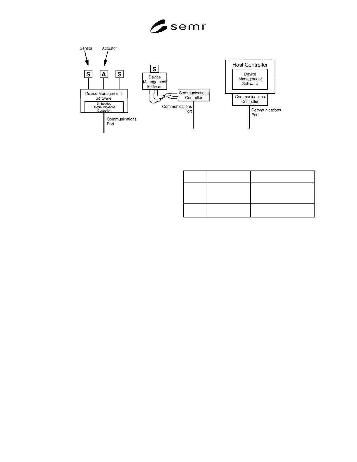
Examples of devices are given in Figure 2.
5.1.5 device model — An abstractio n of a device for
the purpose of understanding it before building it or
using it.
5.1.6 embedded object — An embedded object is sim-
ilar in functionality or purpose to the object in which it
is embedded, or supports the functionality of the object
in which it is embedded. The embedding construct is
utilized solely for purposes of documentation structure
and understanding. As such, it does not imply any
direct relationship, inheritance, similarity in structure,
or connectivity in addressing scheme between the em-
bedded object and the object in which it is embedded.
5.1.7 instance — A specific and real occurrence of an
object.
5.1.8 manufacturer — In the context of this document,
this refers to the manufacturer of the device.
5.1.9 object — An entity with a specific set of data
and behaviors. Objects may be physical or conceptual.
An object may be described in terms of its attributes,
services it provides, and behavior it exhibits.
5.1.10 service — A function offered or supported by
an object. A service consists of a sequence of service
primitives, each described by a list of parameters. A
service excludes definition of message structure and
protocol.
5.1.11 state diagram — A means of representing state
transitions, where the boxes represent states and the
arrows represent transitions between states.
5.2 Data Type Terminology — Unless otherwise
noted, data type terminology defined in SEMI E39 will
be used in this document. The following terminology
will also be used:
5.2.1 Boolean (BOOL) — A binary bit representing 0
and 1 corresponding to FALSE and TRUE or
DISABLE and ENABLE respectively.
5.2.2 byte — A string of eight adjacent bits,
interpreted as a unit and often representing a character.
5.2.3 character — A text symbol, letter, digit, or mark
used to represent, control, or organize information that
is one byte in length.
5.2.4 character string — A text string.
SEMI E54.1-1000 © SEMI 1996, 20003
Figure 2
Examples of Devices
5.2.5 data type — An unsigned short integer formatted
as an enumerated byte to specify attribute data format.
The intended use of this attribute type is in cases where
an attribute, or set of attributes, may be defined,
allowing for more than one level of support (e.g., INT
or REAL). The following values are defined:
0=INT
1=REAL
2=USINT
3=SINT
4=DINT
5=LINT
6=UINT
7=UDINT
8=ULINT
9=LREAL
10–99=reserved for CDM
100–199=reserved for SDMs
200–255=manufacturer-specified
5.2.6 data units — An unsigned integer enumerated to
specify attribute data units. The intended use of this
attribute type is in cases where an attribute, or set of
attributes, may be defined, allowing for more than one
unit’s context. The values are defined in Appendix 1 of
this document.
5.2.7 date — A data structure of four bytes used to
represent a calendar date. Table 1 defines the format of
the date data type.
Table 1 Date Format
Data # Description Range
0–1 Year Unsigned Integer < 65,536
2 Month Unsigned Integer
(range of 1 to 12)
3 Day Unsigned Integer
(range of 1 to 31)
5.2.8 Double Integer (DINT) — An integer, four bytes
long, in the range -2
31
to 2
31
-1.
5.2.9 enumerated byte — A byte with assigned
meaning to the values 0 through 255. May take on one
of a limited set of possible values.
5.2.10 full scale range — The defined 100% value of
an attribute in its assigned units. This value is not
necessarily the maximum value for the attribute. As an
example, the indicated flow attribute value may attain
120% of the full scale range.
5.2.11 Last Valid Value (LVV) — The most recent
value successfully assigned to an attribute.
5.2.12 Long Integer (LINT) — An integer, eight bytes
long, in the range -2
63
to 2
63
-1.
5.2.13 Long Real (LREAL) — A double floating point
number, 8 bytes long, as defined by IEEE 754.
5.2.14 nibble — A string of four adjacent binary bits.
5.2.15 null character — A byte with a value of zero.
5.2.16 Real (REAL) — A floating point number, 4
bytes long, as defined by IEEE 754.
5.2.17 Short Integer (SINT) — An integer, one byte
long, in the range -128 to 127.