semi合集-English.pdf - 第7293页
SEMI MF951-0305 © SEMI 2003, 2005 4 Figure 2 Test Plan B 8.3 Test Plan C 8.3.1 This test plan consists of measurem ents at each of the five measurement positions defined in Plan B of both SEMI MF81 and DIN 504 35 and in …
SEMI MF951-0305 © SEMI 2003, 2005 3
8 Test Plans
8.1 Test Plan A
8.1.1 This test plan consists of measurements (1) at the center of the wafer, located within 3 mm of the intersection
of any two diameters that are at least 45 apart, and (2) at one position 10.0 ± 1 mm from the sample periphery on
one of the diameters parallel with or perpendicular to the major flat (or, for notched wafers, perpendicular to or
parallel with the notch axis).
8.1.2 The positions of edge measurement sites are determined by the distance from the sample periphery to the
center of the aperture.
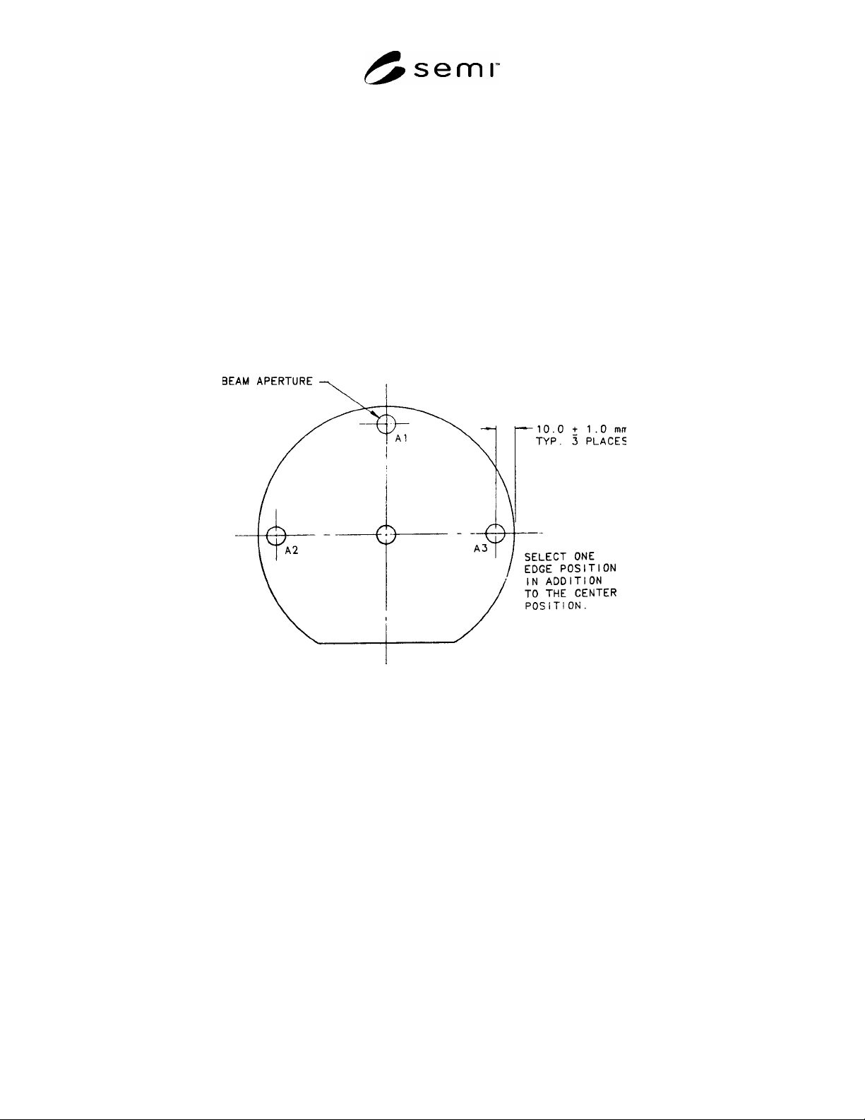
8.1.3 The position A1 on the diameter perpendicular to the major flat (parallel with the notch axis) and at the side of
the wafer opposite the major flat (or notch) is preferred (see Figure 1). Positions A2 and A3 on the diameter parallel
with the major flat (perpendicular to the notch axis) may be selected to replace position A1 if agreed to by both
customer and supplier. Specify Test Plan A1, Test Plan A2, or Test Plan A3 depending on the position selected.
8.1.4 When an interfering minor flat is present, locate the edge position as though the minor flat were not present.
Figure 1
Test Plan A
8.2 Test Plan B
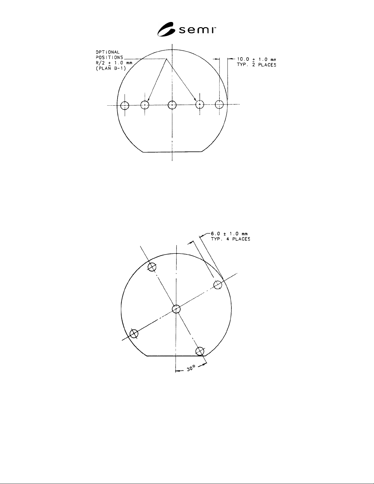
8.2.1 This test plan consists of measurements at the center of the wafer, located within 3 mm of the intersection of
any two diameters that are at least 45 apart, and at two positions 10.0 ± 1 mm from the sample periphery on each
end of the diameter parallel with the major flat (or, for notched wafers, perpendicular to the notch axis) (see Figure
2).
8.2.2 In addition, two optional measurements may be made at the half radius [(R/2) ± 1 mm] positions on the same
diameter of the wafer. If made, these optional measurements must be in addition to measurements at the center and
two edge positions. Customer and supplier must agree on the use of measurements at R/2 positions. Specify Test
Plan B1 when using all five positions.
8.2.3 When an interfering minor flat is present, locate the edge position as though the minor flat were not present.
SEMI MF951-0305 © SEMI 2003, 2005 4
Figure 2
Test Plan B
8.3 Test Plan C
8.3.1 This test plan consists of measurements at each of the five measurement positions defined in Plan B of both
SEMI MF81 and DIN 50435 and in both SEMI MF533 and DIN 50441/1.
8.3.2 Edge position tolerances are ±1 mm; center position shall be within 3 mm of the intersection of any two
diameters which are at least 45° apart (see Figure 3).
Figure 3
Test Plan C
8.4 Test Plan D
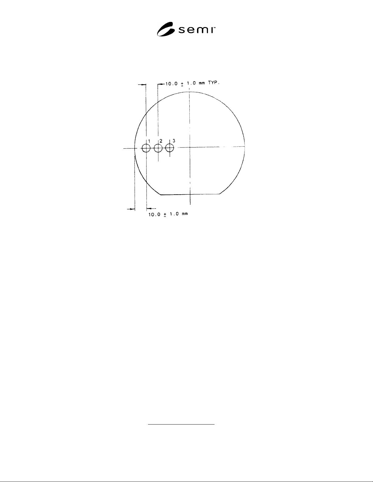
8.4.1 This test plan consists of measurements at a series of points between the edge and center of the wafer along
the diameter parallel with the major flat (or perpendicular to the notch axis) (see Figure 4).
8.4.2 The first position, nearest sample periphery, shall be located in the same manner as Position A2 of Plan A (see
Figure 1).
SEMI MF951-0305 © SEMI 2003, 2005 5
8.4.3 Position spacing shall be in 10 cm steps, center-to-center, continuing to within 5 mm of the sample center.
8.4.4 Position numbering begins at the edge (1) and is sequenced toward the center position.
8.4.5 If a minor flat is located near Position 1, begin sequencing at the opposite edge.
Figure 4
Test Plan D
9 Procedure
9.1 Select one of the test plans defined in §8.
9.2 For referee tests, mark the side of the test slice facing the spectrophotometer infrared source in a noninterfering
manner.
9.3 Place test slice in the fixture apparatus and position in accordance with the selected test plan.
9.4 If the slice thickness is not known for each test site of the selected test plan to ± 0.5% of the nominal slice
thickness, measure the slice thickness at each test site in accordance with SEMI MF533 or DIN 504441/1. Record
the measured or known thicknesses.
9.5 Direct the spectrophotometer infrared beam through the 7 mm aperture located adjacent to the test slice. Move
the test slice, relative to the stationary beam and aperture, to the first test site of the selected plan. Measure and
record the oxygen content at this test site.
9.6 After making the first measurement, move the test slice, relative to the stationary beam and aperture, to the
remaining test sites of the selected plan. Measure and record oxygen content at each test site.
9.6.1 Keep all controllable instrument parameters constant during a test sequence (number of scans, temperature,
reference slice, resolution, etc.).
9.7 For referee tests, repeat the test plan sequence four additional times.
10 Calculations
10.1 Calculate the radial oxygen variation (ROV), in percent, for the sample plan selected:
10.1.1 Test Plan A — Two Positions (Figure 1):
100
ValueCenter
ValueCenter Value Edge
ROV (1)