semi合集-English.pdf - 第4218页
SEMI F74-1103 © SEMI 2002, 2003 5 7.9.2 A materi al testing m achine is used to m a ke a defect on the surface. In place of a pyramid-shaped indenter for hardness m easurement, a wedged shaped indenter, specifically desi…
SEMI F74-1103 © SEMI 2002, 2003 4
7.4.5 Repeat Sections 7.4.1 through Section 7.4.4 for a
total of 5 cycles.
7.4.6 Sample quantity: 3 samples
7.5 Repeatability of Sealing System
7.5.1 Photograph mating surfaces at 10×
magnification.
7.5.2 Perform initial inboard leak test on sealing
system per Section 7.2.1.
7.5.3 A sequence of 10 make and remake cycles shall
be performed on the same sealing system.
NOTE 5: Replace seal after each cycle if recommended by
manufacturer.
7.5.4 Perform internal leak test per Section 7.2.1 after
each make and remake cycle.
7.5.5 Record all visible damage of the mating surfaces
in the form of scratches, burrs, or other particles
photographed after the different intervals at 10x
magnification.
7.5.6 Repeat Section 7.5.2 through Section 7.5.4 three
additional times using a new set of mating surfaces
each time.
NOTE 6: Replace seal after each cycle if recommended by
manufacturer.
7.6 Shock and Vibration Test Method
7.6.1 This test is designed to evaluate the effects of
random accelerations and sustained vibrations during
shipment of gas systems.
7.6.2 Install seals and assemble per manufacturer’s
instructions. Refer to Figures R1-1, R1-2a~ c, and R1-
3a~ c for test fixtures.
7.6.3 Perform inboard leak test per Section 7.2.1.
7.6.4 Conduct shock test per MIL-STD-810E, Method
516.4, Section I-3.1a), procedure I (functional shock),
using terminal-peak saw-tooth shock pulse for ground
equipment operation test.
7.6.5 Perform inboard leak test per Section 7.2.1.
7.6.6 Conduct vibration test per MIL-STD-810E,
Method 514.4, procedure 1 (basic transportation). Test
duration: 1 hour per 1,609 km (1000 miles) of
transportation in each directional axis.
7.6.7 Perform inboard leak test per Section 7.2.1.
7.6.8 Sample quantity: 3
7.7 Seal Preload Safety Factor
7.7.1 This test evaluates the effects of under-tightening
and over-tightening a seal connection.
7.7.2 Install seal and assemble to 80% of the
manufacturer’s sealing load (e.g. torque).
7.7.3 Perform inboard leak test per Section 7.2.1.
7.7.4 Disassemble and repeat using a new seal for each
test.
7.7.5 Sample quantity: 3
7.7.6 Using the same components, install a new seal
and assemble to 120% of the manufacturer’s sealing
load.
7.7.7 Perform inboard leak test per Section 7.2.1. and
note any form of deformation or damage to the seal
connection. Replace connection for subsequent tests if
connection is damaged.
7.7.8 Disassemble and repeat using a new seal for each
test.
7.7.9 Sample quantity: 3
7.8 Torsion Test
7.8.1 This test is designed to measure whether the
sealing system can maintain leak integrity when torque
is applied to an adjacent component or position.
7.8.2 Install seal and assemble per manufacturer’s
instructions. Refer to Figures R1-1, R1-2a~ c, and R1-
3a~ c for test fixtures.
7.8.3 Place a stationary digital torque wrench on the
adjacent component position to measure the torque
applied as make up takes place. Location of placement
is seen in Figure R1-1.
7.8.4 Test per Section 7.2.1.
7.8.5 Rotate the adjacent component in a clockwise
direction until 57.6 cm-kgf (50 in-lbf; 5.649 Nm) torque
is measured on the stationary torque wrench.
7.8.6 Test per Section 7.2.1.
7.8.7 Rotate the adjacent component in a
counterclockwise direction until 57.6 cm-kgf (50 in-lbf;
5.649 Nm) torque is measured on the stationary torque
wrench.
7.8.8 Test per Section 7.2.1.
7.8.9 Repeat 7.8.5 through 7.8.8 with 115.2 cm-kgf
(100 in-lbf; 66.355 Nm) torque.
7.8.10 Sample quantity: 3
7.9 Surface Defect Test
7.9.1 This test method is for evaluating the robustness
of sealing technologies for gas delivery systems used in
semiconductor manufacturing against surface defects
which could occur during normal handling in the field.
SEMI F74-1103 © SEMI 2002, 2003 5
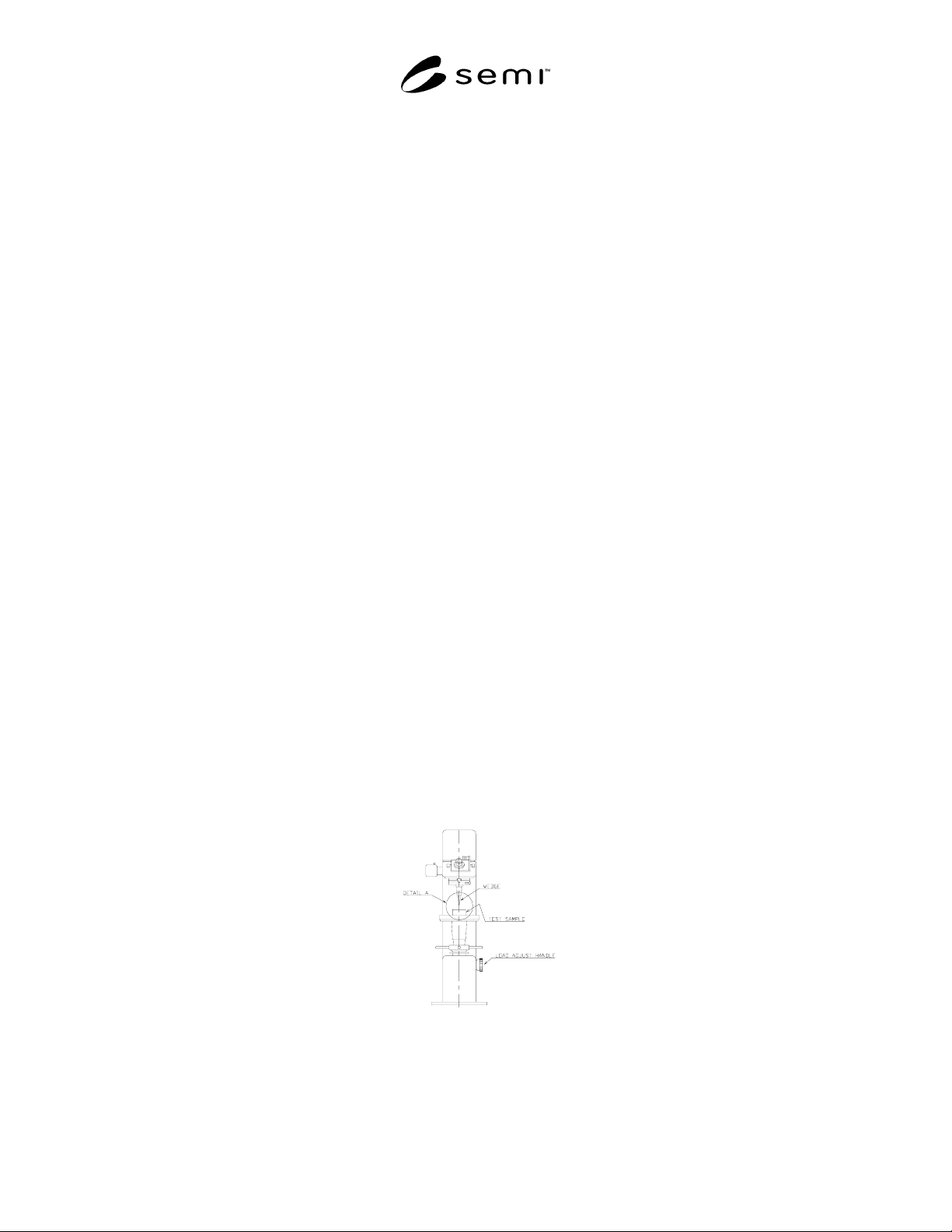
7.9.2 A material testing machine is used to make a
defect on the surface. In place of a pyramid-shaped
indenter for hardness measurement, a wedged shaped
indenter, specifically designed for this test, is installed
in the adjustable-load hardness measurement equipment
shown in Figure 1 and is used to make a surface defect
on test sample.
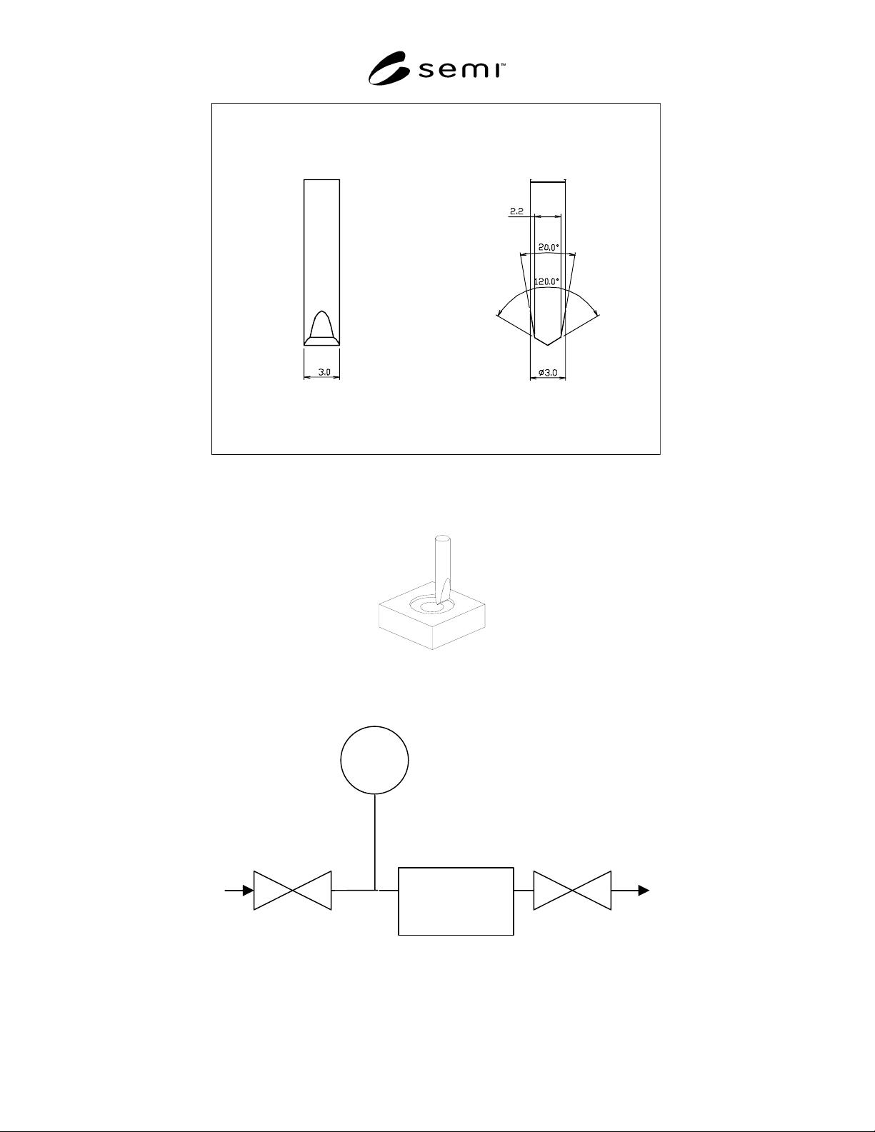
7.9.3 The indenter shall meet the dimensional
requirement shown in Figure 2. The indenter shall have
a minimum hardness of 500 Vickers.
7.9.4 This test defaces only the seal face of the
component, and determines the size of the surface
defect as well as the corresponding leak. In this way,
the degree of weakness of the component’s seal face, as
well as the extent to which the leak can be stopped
depending on defect size, can be determined, making it
possible to evaluate the robustness of the sealing
technology being tested.
7.9.5 Equipment shown in Figure 1 and Figure 2 is
used to make a defect on the surface of the seal face of
the component or substrate.
7.9.6 Load levels are 2, 4, 6, 8 kgf, (19.61, 39.23.
58.84, 78.45 N) and add 2 kgf (19.61 N) incrementally
until leaking occurs. The test sample should be
tightened according to the manufacturer’s installation
manual.
7.9.7 A leak test is performed on the sample according
to the procedure in SEMI F1. As this document is a test
method, not a specification, only the procedure in SEMI
F1 applies.
7.9.8 Correlation between the load and the leak is
determined.
7.9.9 Surface defect size (depth and width) is measured
using surface roughness measuring equipment for
reference.
7.10 Particle Cleanliness After Seal Make-up
7.10.1 The purpose of this test is to verify the particles
generated during a sealing-system compression cycle.
This test involves testing for particles in situ, while
compressing a sealing system.
7.10.2 Test per SEMASPEC 90120390B-STD. Use a
flow-through testing apparatus that is seal-specifically
designed for use in this test, in place of a valve.
7.10.3 Testing must be performed in a Class 100 (or
better) environment in order to obtain low background
counts before the seals are tightened to the substrate.
7.10.4 Follow test protocol in Test Method for Particle
Contribution (see Related Documents) with the
exception that a flow-through bypass fixture must be
attached “finger-tight” to a test substrate before
obtaining a background count.
7.10.5 The testing apparatus with the seals to be tested
must be purged with 0.01 µm filtered gas for sufficient
time so as to remove all inherent particles present
during installation.
7.10.6 Once the lowest possible background count has
been generated, the flow-through test device must be
tightened to the seal manufacturer’s
specifications
while gathering particle counts from the particle
counter. It is recommended that the counts are recorded
via a data acquisition device to allow the user to
compress the seals while the particles are being
recorded.
7.10.7 This test is for comparison purposes only
between data generated at a common facility with
common test setup.
Figure 1
Load Adjustable Hardness Measuring Equipment
SEMI F74-1103 © SEMI 2002, 2003 6
(mm)
Figure 2
Dimension of the Wedge-Shaped Indenter
Figure 3
Wedge and Test Sample (Component or Substrate)
Maximum
rated
working
pressure or
5000 PSI
GAS
SUPPLY
VENT TO
VACUUM
ISOLATION
VALVE
PT
TEST
SAMPLE(S)
ISOLATION
VALVE
Figure 4
Pressure Cycling Test Rig