semi合集-English.pdf - 第6959页
SEMI S8-0705 © SEMI 1995, 2005 56 Section 9: Hand Contr ol Location Section Indicator Figure 9.1.3 Location of frequentl y used controls. Maximum r eaches are ind icated for various heights. Reach es are measured from th…
SEMI S8-0705 © SEMI 1995, 2005 55
Section 8: Display Location
Section Indicator Figure
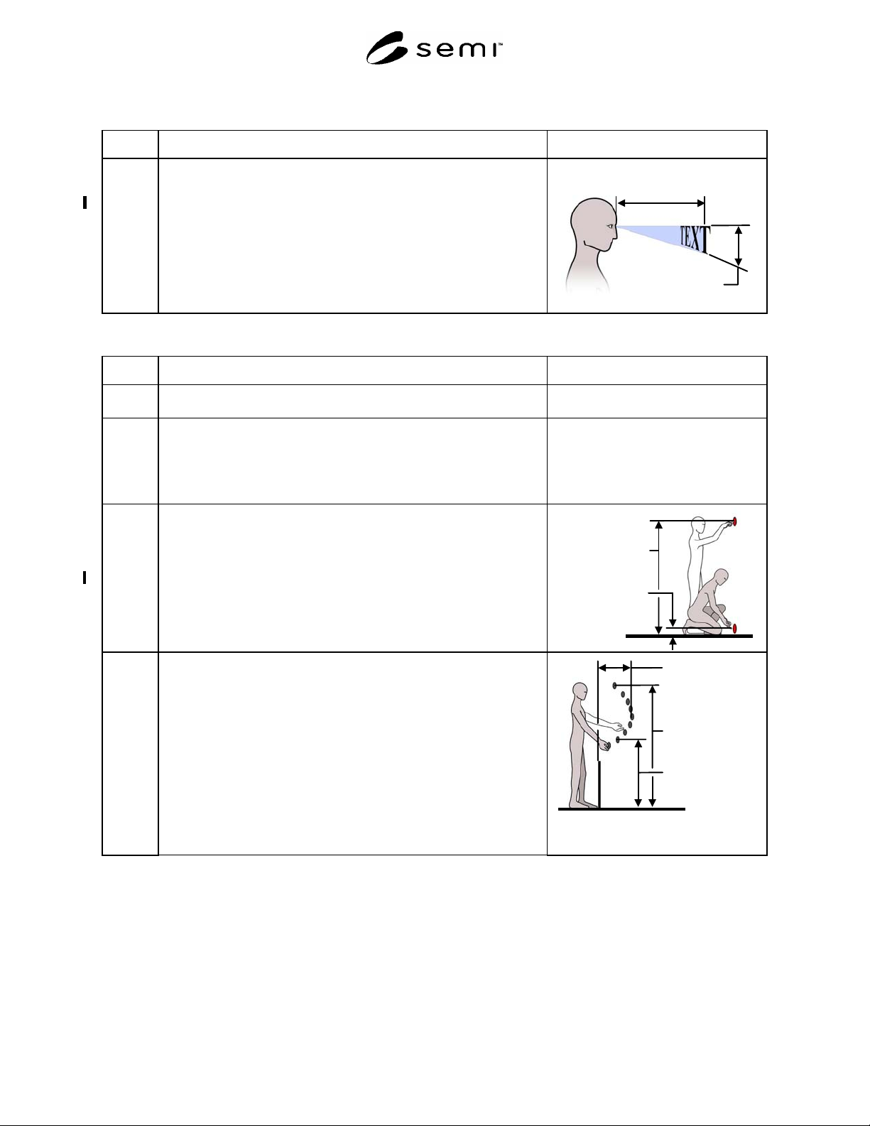
8.3.3 Character height (All characters other than Chinese, Korean and
Japanese.)
Acceptance criterion: character height is greater than or equal to the
viewing distance divided by 215
Recommended viewing distance is between 457 mm (18 in.) and 762 mm
(30 in.).
Viewing distance 457-
762 mm
(18-30 in.)
Character height =
viewing distance
divided by 143
Section 9: Hand Control Location
Section Indicator Figure
9.0 Hand Control Location (These criteria only apply to controls, tools, and
materials accessed for routine production operation and maintenance.)
9.1 Standing station
NOTE: A standing station is one where the machine operator can
assume a standing posture or a seated posture in a tall stool,
which places the operator at approximately the same stature.
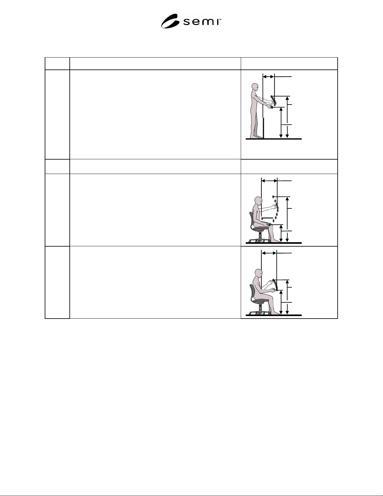
9.1.1 Vertical location of very infrequently used controls (controls used less
often than once every 24 hours) measured from the standing surface to the
centerline of the control.
Acceptance criteria: maximum 1640 mm (64.5 in.).
minimum 0 mm (0 in.).
Minimum 0 mm
(0 in.)
Maximum 1640
mm
(64.5 in.)
9.1.2 Location of infrequently used and/or critical controls. Maximum reaches
are indicated for various heights. Reaches are measured from the leading
edge of the equipment or obstacle.
Acceptance criteria: controls should not be located above 1638 mm (64.5
in.) or below 838 mm (33 in.).
NOTE A: Interpolate for intermediate values.
NOTE B: Reach distances should be measured from the leading edge of
the machine housing or obstructions between the machine
operator and the control. Obstructions include keyboard trays,
drip trays, machine anti-vibration pads and load-bearing pads.
NOTE C: See Figure 9.1.2 for maximum recommended reaches.
Minimum 838
mm
(33 in.)
Maximum 483
mm
(19 in.)
Maximum 1638
mm
(64.5 in.)
SEMI S8-0705 © SEMI 1995, 2005 56
Section 9: Hand Control Location
Section Indicator Figure
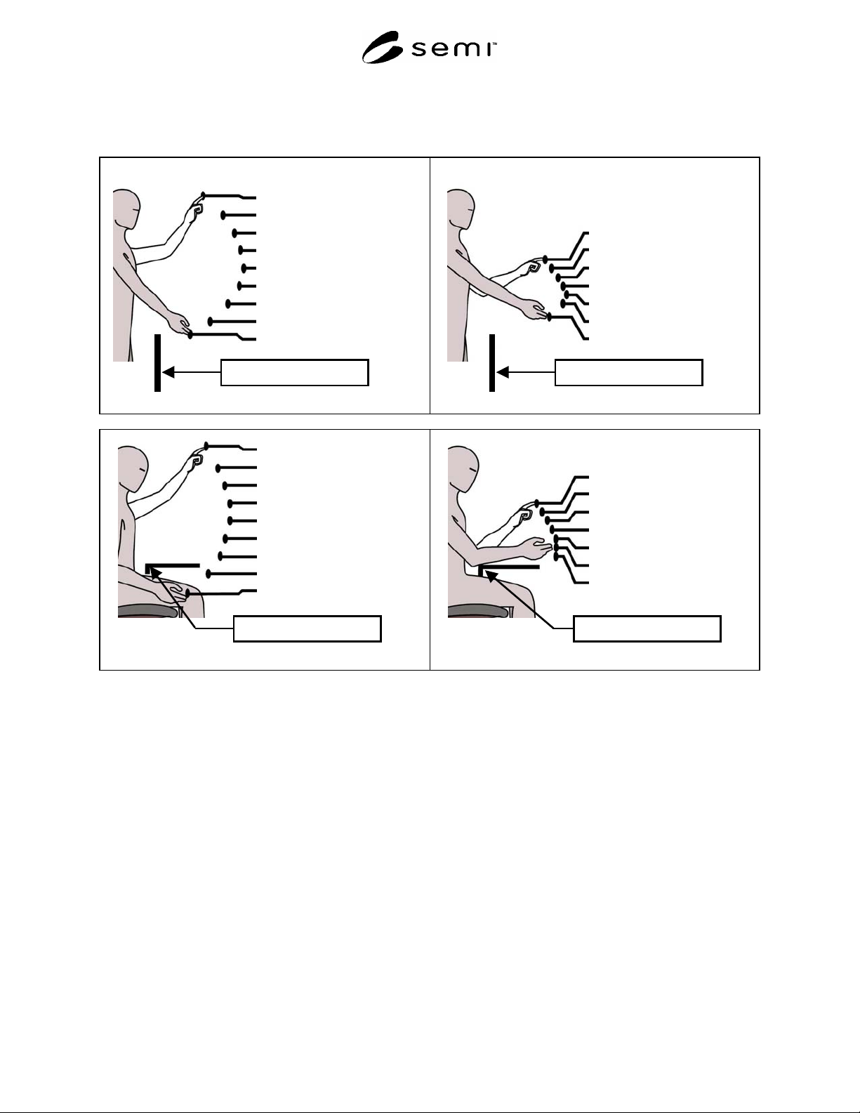
9.1.3 Location of frequently used controls. Maximum reaches are indicated for
various heights. Reaches are measured from the leading edge of the
equipment or obstacle.
Acceptance criteria: controls should not be located above 1270 mm (50
in.) or below 940 mm (37 in.).
NOTE A: Interpolate for intermediate values.
NOTE B: Reach distances should be measured from the leading edge of
the machine housing or obstructions to the center of the
control. Obstructions include keyboard trays, drip trays,
machine load bearing pads and anti-vibration pads.
NOTE C: See Figure 9.1.3 for maximum recommended reaches.
Minimum 940
mm
(37 in.)
Maximum 406
mm
(16 in.)
Maximum 1270
mm
(50 in.)
9.2 Seated station (Note: A seated station is one where a short cylinder
office-style chair is used).
9.2.1 Location of infrequently used and/or critical controls. Maximum reaches
are indicated for various heights. Reaches are measured from the leading
edge of the work surface or obstacle.
Acceptance criteria: Controls should not be located above 1397 mm (55
in.) or below 533 mm (21 in.).
NOTE A: Interpolate for intermediate values.
NOTE B: See Figure 9.2.1 for maximum recommended reaches.
Minimum 533
mm
(21 in.)
Maximum 483
mm
(19 in.)
Maximum 1397
mm
(55 in.)
9.2.2 Location of frequently used controls. Maximum reaches are indicated for
various heights. Reaches are measured from the leading edge of the work
surface or obstacle.
Acceptance criteria: controls should not be located above 1067 mm (42
in.) or below 762 mm (30 in.).
NOTE A: Interpolate for intermediate values.
NOTE B: See Figure 9.2.2 for maximum recommended reaches.
Minimum 762
mm
(30 in.)
Maximum 419
mm
(16.5 in.)
Maximum 1067
mm
(42 in.)
SEMI S8-0705 © SEMI 1995, 2005 57
Section 9: Hand Control Location Figures
Coordinates given for hand control locations. Height (vertical measurement from standing surface to center of control), Depth
(horizontal measurement from leading edge of work surface to the center of control)
Height and depth of controls
1638, 254 mm
(64.5, 10.0 in.)
1524, 368 mm
(60, 14.5 in.)
1422, 432 mm
(56, 17.0 in.)
1321, 470 mm
(52, 18.5 in.)
1219, 483 mm
(48, 19.0 in.)
1118, 470 mm
(44, 18.5 in.)
1016, 394 mm
(40, 15.5 in.)
914, 292 mm
(36, 11.5 in.)
838, 178 mm
(33, 7.0 in.)
Leading edge of workstation
Figure 9.1.2 Infrequently used standing control reaches
Height and depth of controls
1270, 292 mm
(50, 11.5 in.)
1219, 330 mm
(48,13.0 in.)
1168, 368 mm
(46, 14.5 in.)
1118, 394 mm
(44, 15.5 in.)
1067, 406 mm
(42, 16.0 in.)
1016, 394 mm
(40, 15.5 in.)
940, 318 mm
(37, 12.5 in.)
Leading edge of workstation
Figure 9.1.3 Frequently used standing control reaches
1397, 356 mm
(55, 14.5 in.)
1270, 432 mm
(50, 17.0 in.)
1168, 470 mm
(46, 18.5 in.)
1067, 483 mm
(42, 19.0 in.)
965, 483 mm
(38, 19.0 in.)
864, 470 mm
(34, 18.5 in.)
762, 445 mm
(30, 17.5 in.)
660, 381 mm
(26, 15.0 in.)
533, 254 mm
(21, 10.0 in.)
Leading edge of workstation
Figure 9.2.1 Infrequently used seated control reaches
1067, 330 mm
(42, 13.0 in.)
1016, 368 mm
(40, 14.5 in.)
965, 394 mm
(38, 15.5 in.)
914, 406 mm
(36, 16.0 in.)
864, 419 mm
(34, 16.5 in.)
813, 419 mm
(32, 16.5 in.)
762, 419 mm
(30, 16.5 in.)
Leading edge of workstation
Figure 9.2.2 Frequently used seated control reaches