semi合集-English.pdf - 第2762页
SEMI E98-1102 © SEMI 2000, 2002 27 10.5.5.2 Additional details of the BE HAVIOR state are shown in Figure 18. 10.5.5.3 In addition to the states show n above, the AbstractEquipm entModule has an ARAMS state model, de fin…
SEMI E98-1102 © SEMI 2000, 2002 26
10.5.4.8.2 Both process recipes and service recipes
may be associated with specific setups.
10.5.4.8.3 Recipes of the class “/SETUP/” may be used
to put the AbstractEquipmentModule into a specific
state. The user uses the name of the setup for
scheduling work. This is captured in the attribute
ProcessSetup.
10.5.4.9 Recipes
10.5.4.9.1 An AbstractEquipmentModule may provide
recipe execution services and the ability to accept,
store, verify, select, and run Execution Recipes (SEMI
E42). This ability is required for AbstractEquipment-
Modules with a ProcessType of “Process” or “Measure-
ment”. Where provided, recipes and recipe execution
shall comply with the fundamental requirements for the
Execution Recipe and Recipe Executor as specified in
SEMI E42 (RMS).
10.5.4.9.2 Some equipment performs its process in
three stages, which can be characterized as preamble,
main process, and postamble, where the preamble is
preparation for the stable part of the process, and the
postamble takes care of the transition from the stable
part of the process until it is ready to unload the
material. In a furnace, for example, the preamble could
include both the period where it is ramping to attain the
setpoint temperature and the gas flow setpoints. A
fourth stage is sometimes defined to handle abnormal
terminations.
10.5.4.9.3 From a recipe standpoint, these different
stages can be represented as different sections of a
single recipe or as separate recipes linked to a main
recipe.
10.5.4.10 Mechanical Dry Run
10.5.4.10.1 The AbstractEquipmentModule shall
support the capability to do a mechanical dry run. This
allows the material handling subsystems and software
functions to be exercised and tested without requiring
full process hookups and without using process
consumables. Typically this is done through a specially
designated recipe that allows time settings and does not
use settings for temperature, gases, plasmas, water, etc.
In some cases, it may require a recipe of a special class,
such as “/DRYRUN/”. Environmental subsystems such
as vacuum, nitrogen purge, particle detection
subsystems, etc. must be allowed to function normally
during a mechanical dry run.
10.5.4.10.2 Dry runs shall be prohibited during the
ARAMS Manufacturing state.
10.5.4.10.3 Certain types of tools may need to modify
the definition of the mechanical dry run to address
special issues in a way that still satisfies the objectives.
Equipment documentation shall specify the method
used to satisfy this requirement.
10.5.5 AbstractEquipmentModule State Model
10.5.5.1 The AbstractEquipmentModule inherits the
Operational State Model of the AbstractEquipment-
Subsystem. In addition to the concurrent substates of
SERVICE, the AbstractEquipmentModule adds the
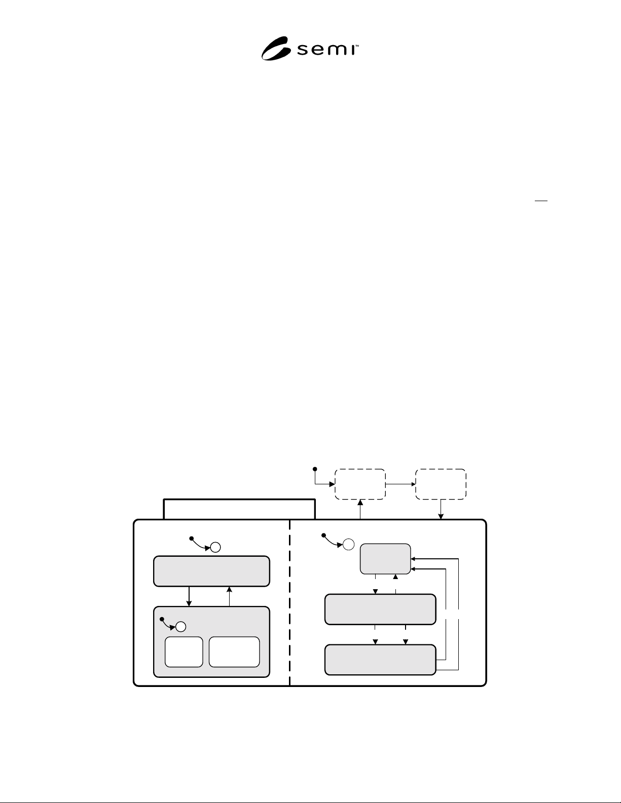
BEHAVIOR state. Figure 17 shows the Operational
State Model with its two concurrent substates.
OPERATIONAL
SERVICE
BEHAVIOR
INITIALIZATION
POWER
DOWN
ACTIVE
IDLE
12
25
13
INACTIVE
2220
C
24
11
C
1
IN SERVICE
3
USER
SELECT
EQUIPMENT
SELECT
2
C
4
OUT OF
SERVICE
Figure 17
AbstractEquipmentModule Operational State Model
SEMI E98-1102 © SEMI 2000, 2002 27
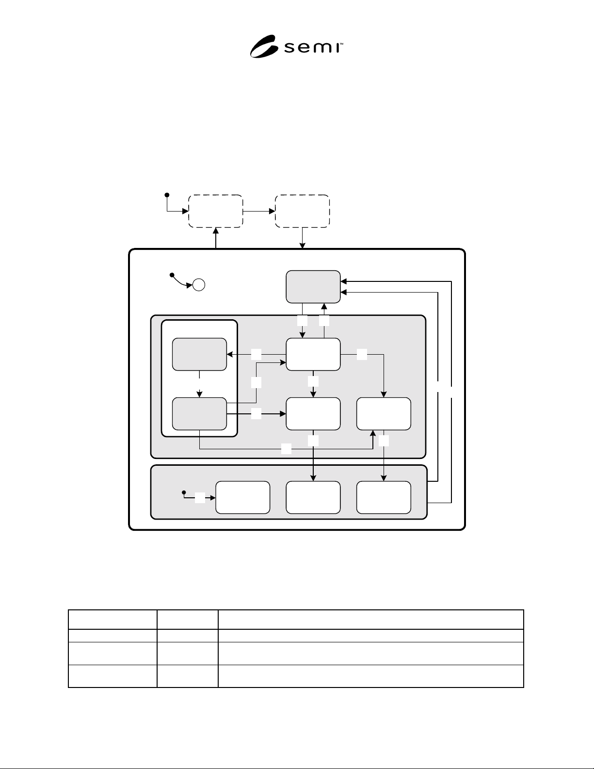
10.5.5.2 Additional details of the BEHAVIOR state are shown in Figure 18.
10.5.5.3 In addition to the states shown above, the AbstractEquipmentModule has an ARAMS state model, defined
in SEMI E58. The diagram for the ARAMS state model for modules is shown in Figure 6 in that document.
10.5.5.4 AbstractEquipmentModule Behavior State
10.5.5.4.1 The details of the BEHAVIOR state are shown in Table 11. POWERDOWN and INITIALIZING states
are included in the table to simplify comparisons with the ARAMS State Model and the Operational State Model
defined in SEMI E58. State models are initialized during the INITIALIZATION state. Communications shall be
initialized before the ARAMS state model is initialized in order to allow reporting of power down events.
ACTIVE
BEHAVIOR
IDLE
ACTIVE
SERVICE
12
PAUSE
PAUSING 14
25
13
16
INACTIVE
ABORTINGSTOPPING
19
ABORTEDSTOPPED
21
2220
IDLE WITH
ALARMS
24
18
17
23
PAUSED
15
INITIALIZATION
POWER
DOWN
C
11
Figure 18
Behavior State
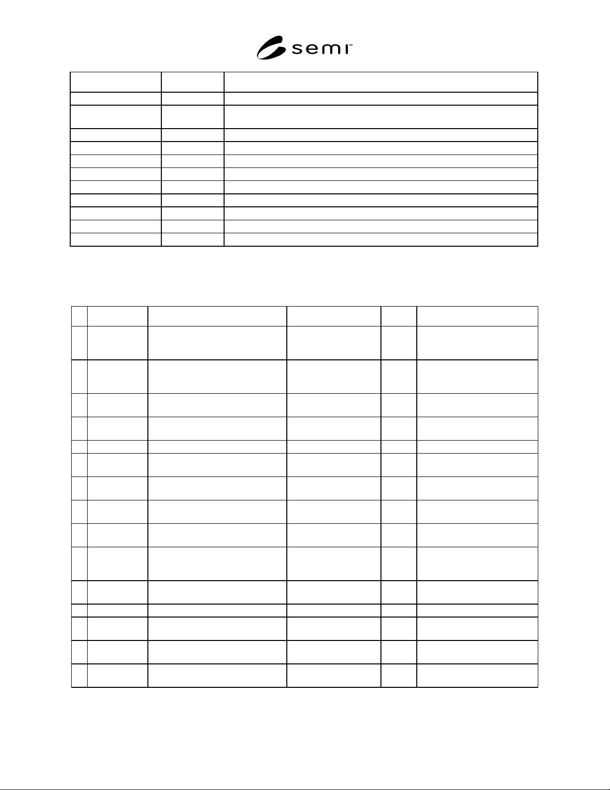
10.5.5.4.2 Table 11 defines the substates of the BEHAVIOR state.
Table 11 AbstractEquipmentModule Behavior State Definitions
State Name Superstate Definition
POWERDOWN None The AbstractEquipmentModule is powered off.
INITIALIZING None The AbstractEquipmentModule system, including hardware and software, is being
initialized. It is not ready to accept instructions.
IDLE IN SERVICE The AbstractEquipmentModule is fault free and able to accept instructions to perform
a manual or automated procedure that may change its physical state.
SEMI E98-1102 © SEMI 2000, 2002 28
State Name Superstate Definition
ACTIVE IN SERVICE The AbstractEquipmentModule is performing activities that change its physical state.
ACTIVE SERVICE ACTIVE While assigned to manufacturing, the AbstractEquipmentModule may only perform
its normal process.
PAUSE ACTIVE The AbstractEquipmentModule has received instructions to pause its activity.
PAUSING PAUSE The AbstractEquipmentModule is in the process of putting itself into a safe state.
PAUSED PAUSE The AbstractEquipmentModule is in a safe state.
STOPPING ACTIVE The AbstractEquipmentModule has begun the stop operation.
ABORTING ACTIVE The AbstractEquipmentModule has started the abort operation.
INACTIVE IN SERVICE The AbstractEquipmentModule has completed its stop or abort operation.
IDLE WITH ALARMS INACTIVE The AbstractEquipmentModule is idle but has a fault condition.
STOPPED INACTIVE The AbstractEquipmentModule has completed the stop operation.
ABORTED INACTIVE The AbstractEquipmentModule has completed the abort operation.
10.5.5.5 AbstractEquipment Module State Transition Table — Table 12 defines the state transitions for the
AbstractEquipmentModule Operations state model.
Table 12 AbstractEquipmentModule Behavior State Transitions
# Previous State Trigger New State Action(s) Comment
11 Any State model is initialized. depends on previous
state and current
condition
None See Section 9.5.2.2.
12 IDLE An activity changing the physical
state of the module is started.
ACTIVE SERVICE None Substates of ACTIVE
SERVICE are module
dependent.
13 ACTIVE
SERVICE
All activities changing the physical
state are completed without fault.
IDLE None IDLE is fault-free.
14 ACTIVE
SERVICE
The module received instructions to
pause its activity.
PAUSING None The module is responsible for
reaching a safe state.
15 PAUSING All activity is paused. PAUSED None
16 PAUSED The module has received instructions
to resume its activity.
ACTIVE SERVICE None
17 PAUSED The module has received instructions
to stop its activity.
STOPPING None The module is responsible for
reaching a safe state.
18 PAUSED The module has received instructions
to abort its activity.
ABORTING None
19 ACTIVE
SERVICE
The module has received instructions
to stop its activity.
STOPPING None
20 STOPPING The Stop operation has completed
and all material started has been
returned to its proper destination.
STOPPED None
21 ACTIVE
SERVICE
The module has received instructions
to abort its activity.
ABORTING None The module is responsible for
reaching a safe state.
22 ABORTING Completion of aborting activity. ABORTED None
23 Any Default entry into INACTIVE IDLE WITH ALARMS None One or more exceptions
detected during initialization.
24 INACTIVE The module received instructions to
return to IDLE.
IDLE None IDLE is fault-free.
25 INACTIVE The module returns to IDLE
automatically.
IDLE None IDLE is fault-free.